Introduction
NODA Intelligent Systems (NODA) is a spin-off company from research within artificial intelligence at Blekinge Institute of Technology, Sweden. NODA was founded in 2005 and currently has offices in Karlshamn and Malmö in Sweden.
NODA has customers and partners throughout Europe, North America and Asia. The focus of NODA is to develop and market AI-based solutions for thermal systems like district heating and cooling, heat pumps and gas.
In addition, NODA has a strong relationship with universities and research institutes in research and innovation. NODA works with several partners and customers to implement its technology and market approach. These partners range from large global companies to local and regional energy companies or building owners.
Traditionally, the focus of NODA has primarily been on district heating. Still, the last few years have seen an increased focus on hybrid systems based on thermal processes such as combined heat and power, heat pumps and excess heat extraction. This gives NODA a broad range of working knowledge of different types of systems and how they can be combined.
NODA works in the production and delivery chain regarding product development from core research to operational products and routinely participates in international and national research and innovation projects.
Products and services
NODA works with a wide variety of partners and we implement hardware or software integrations wherever needed. In addition, by avoiding tying oneself to a particular equipment manufacturer and relying on in-house software development, NODA is flexible enough to change when new requirements call for change.
EnergyView
This tool has evolved over the years. Its inception was back in 2009 under the working name Linckii. EnergyView is the primary tool for interacting with data stored from communication with field equipment and the output from our machine learning algorithms.
We deploy each customer domain on a separate database. Thus, creating partitions between customers to prevent accidental, unauthorized access.
EnergyView allows access to the time-series data through configurable time-series graphs. Users with more than basic access privileges can change most aspects of an installation.
The system also exposes essential objects as a REST API over HTTP. This interface allows for third-party interaction with the system.
My Pages
My Pages is a much simpler tool compared to EnergyView. Its demographic is customers who want a direct answer, not a philosophical discussion surrounding the question.
Here customers can see all control actions the NODA equipment has performed. They can also get an energy analysis of their heating system and energy consumption along with time-series graphs of their indoor sensors.
Self-host
![]()
The purpose of the NODA Self-host is to provide customers with an option to run the core components of the NODA system in their environment as their responsibility. This includes;
- API Server (Aapije)
- Program Server (Juvuln and Malgomaj)
- DBMS (PostgreSQL 12.0+)
These components are all Open Source and freely available for anyone to use without paying for the software. However, a negotiated support agreement is required for aid in deployment.
In a project, we expect customer-specific integrations and the addition of NODAs proprietary software.
Components such as;
- Machine Learning Algorithms (Kimaera)
- MQTT protocol translation bridges
- User interfaces
Document Notes
All information in this manual, including product data, diagrams, charts, etcetera. represents information on products at the time of publication, and is subject to change without prior notice due to product improvements or other reasons.
The documentation and product are provided on an "as is" basis only and may contain deficiencies or inadequacies. NODA Intelligent Systems AB takes no responsibility for damages, liabilities or other losses by using this product.
Copyright and trademark
© 2024, NODA Intelligent Systems AB.
All rights reserved. No part of the contents of this manual may be transmitted or reproduced in any form by any means without the written permission of NODA Intelligent Systems AB.
Contact information
NODA Intelligent Systems AB Headquarter
Biblioteksgatan 4
374 35 Karlshamn
SWEDEN
- 📞 Phone: +46 454 10 271
- 📧 E-Mail: info@noda.se
NODA Intelligent Systems AB Technical Support
- 📞 Phone: +46 454 10 271
- 📧 E-Mail: support@noda.se
- 🌎 Online: https://www.noda.se
NODA Glossary
This is a glossary of terms used in the NODA documentation.
District heating terminology
| Term | Definition |
|---|---|
| CHP | Combined heat and power, also known as cogeneration, is a system that generates both electricity and heat from a single fuel source, such as natural gas, biomass, or biogas. CHP systems can be more efficient and environmentally friendly than traditional power generation and heating systems. |
| District heating | A system that delivers heat from a central source, such as a CHP plant or a heating plant, to multiple buildings or homes through a network of underground pipes. District heating systems can be more efficient and environmentally friendly than individual heating systems in each building. |
| Heat exchanger | A device that transfers heat from one fluid or medium to another, without the two fluids or media coming into direct contact. Heat exchangers are commonly used in district heating systems to transfer heat from the hot water in the pipes to the water in the building's heating system. |
| Heat meter | A device that measures the amount of heat delivered to a building or home through a district heating system. Heat meters are typically used to bill customers for the heat they consume based on their usage. |
| Heat network | Another term for a district heating system, referring to the network of pipes that delivers heat from a central source to multiple buildings or homes. |
| Pipe insulation | Insulation that is used to wrap the pipes in a district heating system to reduce heat loss and improve efficiency. |
| Primary loop | The portion of a district heating system that carries hot water from the central source, such as a CHP plant or a heating plant, to the substations. |
| Secondary loop | The portion of a district heating system that carries hot water from the substations to the buildings or homes. |
| Substation | A device that is used to control and distribute the heat delivered by a district heating system to multiple buildings or homes. A substation typically includes a heat exchanger, a pump, and other equipment to regulate the flow of heat and maintain the desired temperature in the heating system. |
| Temperature control valve | A valve that is used to regulate the flow of hot water in a district heating system and maintain the desired temperature in the heating system. |
| Thermal storage | The use of heat storage tanks or other devices to store excess heat generated by a district heating system for later use. Thermal storage can help to smooth out fluctuations in |
IT-infrastructure
| Term | Definition |
|---|---|
| Backup | The process of creating copies of data or other resources in case the original is lost, damaged, or otherwise becomes unavailable. Backups are typically stored on separate devices or media, such as external hard drives or cloud storage, to ensure that they are not lost along with the original. |
| Cloud computing | A model of computing in which users access and use shared resources, such as computing power, storage, and software, over the internet, rather than using their own local resources. Cloud computing can be more cost-effective and scalable than traditional computing models. |
| Data center | A facility that houses and supports the operation of servers, storage systems, and other IT infrastructure. Data centers may be owned and operated by a company, or they may be provided by a third party as a service. |
| Domain name | A unique name that is used to identify a website or other internet resource. Domain names are typically organized into a hierarchy based on the type of resource, such as .com for commercial websites, .gov for US government websites, and .edu for educational websites. |
| Firewall | A security system that monitors and controls incoming and outgoing network traffic based on predetermined security rules. Firewalls are used to protect networks from unauthorized access, malware, and other threats. |
| Infrastructure | The underlying framework or structures that support the operation of a system or service. In the context of IT, infrastructure typically refers to the hardware, software, and other resources that are needed to support the operation of a network or other IT system. |
| Load balancer | A device or software that distributes incoming network traffic across multiple servers or resources to improve the performance and availability of a network or service. Load balancers can use various algorithms to determine how to route traffic, such as round-robin or least connections. |
| Managed service | A service provided by a third party that is responsible for the management and maintenance of a particular aspect of an organization's IT infrastructure, such as security, storage, or networking. Managed services can help organizations to more effectively manage their IT resources and reduce costs. |
| Network segment | A portion of a network that is separated from other parts of the network by a device, such as a switch or router. Network segments can be used to improve the performance and security of a network by isolating traffic and limiting access to certain resources. |
| Protocol | A set of rules or conventions that govern the communication between devices or systems. Protocols define how devices should connect, transmit data, and handle errors. There are many different protocols used in networking and other fields, such as HTTP, SMTP, and FTP. |
| Router | A device that connects multiple networks and forwards data packets between them based on their destination. Routers use routing tables and protocols to determine the most efficient path for data to travel and can also provide security and other networking services. |
| Security group | A collection of rules that define the traffic that is allowed to flow in and out of a network or resource. Security groups can be used to control access to resources and protect them from unauthorized access or attacks. |
| Virtual machine | A software-based simulation of a physical computer that runs on top of a host operating system. Virtual machines allow multiple operating systems or applications to run on a single physical server, providing benefits such as improved resource utilization and easier management. |
| Virtual network | A network that is created and managed entirely within software, rather than using physical networking hardware. Virtual networks can be used to create isolated networking environments within a larger network, or to connect multiple networks together. |
| Virtual private network (VPN) | A private network that is created over a public network, such as the internet. VPNs use encryption and other security measures to protect data transmitted over the network and to provide secure remote access to resources. |
| VLAN | A virtual local area network (VLAN) is a logical grouping of devices that are created within a larger network. VLANs are used to segment a network into smaller, more secure and efficient sub-networks. |
| WAN | A wide area network (WAN) is a network that spans a large geographical area, such as a country or the entire globe. WANs are typically used to connect multiple smaller networks, such as LANs or WLANs, together and can be implemented using various technologies, such as leased lines or satellite links. |
| Web server | A server that is designed to host websites and provide web content and services over the internet. Web servers typically run software, such as Apache or Microsoft IIS, that is responsible for handling requests from clients and serving content in response. |
| WLAN | A wireless local area network (WLAN) is a network that connects devices using wireless technology, such as Wi-Fi. WLANs can be used to provide connectivity within a limited area, such as a home or office, or can be connected to a larger network, such as the internet. |
Modbus terminology
| Term | Definition |
|---|---|
| Address | The location of a register or other data element on a Modbus server. Modbus addresses are typically expressed as 16-bit values, ranging from 0 to 65,535. |
| Client | A device that initiates communication with a Modbus server by sending requests for data or commands. Also known as a master. |
| Command | An instruction or request sent by a Modbus client to a Modbus server. Modbus commands are typically expressed as function codes, which specify the type of operation being requested. |
| Function code | A code that specifies the type of operation being requested in a Modbus command. Modbus function codes range from 0 to 255 and include codes for reading and writing data, diagnostics, and other operations. |
| Latching register | A register that retains its value until it is explicitly overwritten or reset. The specific behavior of latching registers may vary depending on the manufacturer. |
| Master | See "client" |
| Modbus | A communication protocol that is used to exchange data between devices over a variety of communication links, including serial and Ethernet. Modbus is widely used in industrial and building automation systems to enable devices to communicate with each other and exchange data. |
| Non-latching register | A register that does not retain its value after power is removed. The specific behavior of non-latching registers may vary depending on the manufacturer. |
| Register | A location in the memory of a Modbus server that is used to store or retrieve data. Modbus registers are typically 16 bits in size and are addressed using 16-bit values. |
| Server | A device that responds to requests for data or commands from a Modbus client. Also known as a slave. |
| Slave | See "server" |
| Word | A 16-bit value. Modbus registers are typically addressed and accessed as words, rather than individual bytes. |
Introduction

EnergyView is a cloud platform with a user interface (front-end) used to administer NODA's services. The platform consists of several components:
-
Database system (single tenant) based on PostgreSQL.
-
Login system (IdP - identity provider).
-
User interface with a separate view for end users of the product NODA Building, referred to as My pages (Mina sidor).
-
API that enables external systems to interact with NODA.
-
Tools for configuring and administering services and creating reports that visualise data.
-
Integrations for communication with customer installations.
-
Back-end with a software architecture based on microservices that runs in Kubernetes. This document only further describes these services in cases where explaining the relationship to various NODA services is necessary.
The EnergyView platform is of the single tenant type, meaning customers have their own separate databases on separate customer domains. An advantage of this design is that each customer's data is completely separated from other customers' data.
Users
A user can access one or more customer domains. There are two types of users:
-
EnergyView users who have access to EnergyView. These have four different levels of permissions: Basic (see data), Operator (manage settings), Administrator (full access), and API users.
-
My pages users only have access to the My pages/Mina sidor module.
Introduction
EnergyView is a cloud platform with a user interface (front-end) used to administer NODA's services. The platform consists of several components:
-
Database system (single tenant) based on PostgreSQL.
-
Login system (IdP - identity provider).
-
User interface with a separate view for end users of the product NODA Building, referred to as My pages (Mina sidor).
-
API that enables external systems to interact with NODA.
-
Tools for configuring and administering services and creating reports that visualise data.
-
Integrations for communication with customer installations.
-
Back-end with a software architecture based on microservices that runs in Kubernetes. This document only further describes these services in cases where explaining the relationship to various NODA services is necessary.
The EnergyView platform is of the single tenant type, meaning customers have their own separate databases on separate customer domains. An advantage of this design is that each customer's data is completely separated from other customers' data.
Users
A user can access one or more customer domains. There are two types of users:
-
EnergyView users who have access to EnergyView. These have four different levels of permissions: Basic (see data), Operator (manage settings), Administrator (full access), and API users.
-
My pages users only have access to the My pages/Mina sidor module.
Information Model
Each NODA customer has one or more domains on which collected data is stored.
Permission is granted per customer domain, meaning a user can access multiple customer domains. Upon logging in, users with access to numerous customer domains will arrive at a predefined home domain. In the dropdown menu at the top right, users see the domains they have permission for and can switch between domains in the menu (opens in a new window).
This structure means that EnergyView supports customers with one or more customer domains, where each domain has one or more users and one or more customer installations with various services activated.
A customer domain has several collectors, representing objects of a specific type with tags for data. A collector could, for example, mean an indoor sensor, a building, or something else. Collectors can be grouped into groups, which are used in various ways in NODA's services.
erDiagram
    CUSTOMER ||..|{ DOMAIN : "owns/has"
    CUSTOMER ||..o{ USER-ACCOUNT : "owns/has"
    USER-ACCOUNT ||--o{ DOMAIN : "has access to"
    DOMAIN ||--o{ COLLECTOR : contains
    COLLECTOR {
        text name
        text description
        lable type
        representation object
        number local-id
        UUID global-id
        text data-interface-id
    }
    COLLECTOR ||--o{ TAG : has
    TAG {
        text namne
        text description
        text unit
    }
    GROUP }|--|{ COLLECTOR : contains
Data Structure
Data points are systematised in EnergyView using the concepts of tag, protocol, device, and collector described in the sections below.
Tag
Data points are linked to tags, where a tag corresponds to a measured value or a computed value of a specific sort. Examples of a tag are indoor temperature, power, flow, etc. Measured values are saved in the database on a customer domain via tags.
Protocol
The top level of the structure for data storage on a customer domain in EnergyView is called a protocol. A protocol is a list of tags. Protocols define which tags exist and can be seen as a gross list. If a new tag is to be created, this is done by adding it to an existing or new protocol. Protocols are thus a high-level sorting of tags. They could, for example, be IoT sensors, properties, district heating systems, or similar.
Several objects and properties are used for further systematisation, described under Device and Collector below. In our environment at NODA, for example, we have used a master protocol for tags related to buildings, a protocol for indoor sensors, and a protocol for tags from the weather forecast service we use. Currently, tags are referred to as sensors, but it means the same thing.
Device
Under each protocol, devices that use the protocol are defined. A device has a limited subset of the tags on the protocol to which it belongs. Nothing prevents a device under a protocol from having all the tags on the protocol. Still, devices make it possible to systematise the structure of data. Protocols are the gross list of tags, and devices are net lists of tags. Examples of what devices can correspond to are meters, sensors, control systems, etc.
Collector
A collector is a node representing something which communicates data points with NODA, for example, a district heating substation in a multi-dwelling building, a sensor in an office, or something else. Several properties declare a collector:
- Name: Free text.
- Description: Free text.
- Device (see Device above): a collector is a device.
- Object representation: A label that describes what the collector represents, e.g., Residential building, Indoor climate sensor, Heating circuit, Network station, etc.
- Tags: The collector has access to the Device's tags, and it is possible to choose which tags should be activated on the collector.
- Identifiers created by the system:
- Local identifier: A node ID, which is a serial number for the collector on the customer domain.
- Global unique identifier: A UUID, which can be used to identify the collector via communication between different systems.
- Data interface identifier: This is an ID the user can set themselves and is used for matching when an ID comes from an external system. It is thus an ID that an external system has set, for example, a serial number on a sensor or a MAC address.
Sub-collectors
It is possible to define affiliations between collectors according to a parent-child principle. That is, a collector can be the child of another collector. For example, room sensors can be sub-collectors to a collector representing a building.
Groups
A group consists of collectors. A collector can belong to several groups. Groups are used to describe affiliation for collectors.
API
The EnergyView API comprises two distinct interfaces, namely APIv1 and APIv2. Both interfaces are currently maintained and undergo changes while ensuring backward compatibility.
APIv1
This interface, though older, remains in active use and was initially developed to fulfill our internal requirements. It primarily serves as a representation of the underlying structure of the EnergyView database.
The documentation for APIv1 is publicly accessible and can be located here.
APIv2
Introduced as a newer interface, APIv2 does not diminish the utility of the older APIv1. Its inception was a result of the development of our standalone data store solution, NODA Self-host, in 2021.
To facilitate seamless interoperability between EnergyView and the Self-host system, a compatibility interface was required. Consequently, most, though not all, of the Self-host API functionality was implemented in EnergyView.
The documentation for APIv2 is publicly available and can be found here.
Examples
Understanding the API documentation can be challenging without proper context. To mitigate this, we have created a website featuring examples to assist you. This resource, known as NODA by Example, aims to provide clarity and practical demonstrations.
Collector/Node
A collector is a node representing something which communicates data points with NODA, for example, a district heating substation in a multi-dwelling building, a sensor in an office, or something else. Several properties declare a collector:
-
Name: Free text.
-
Description: Free text.
-
Device (see Device above): a collector is a device.
-
Object representation: A label that describes what the collector represents, e.g., Residential building, Indoor climate sensor, Heating circuit, Network station, etc.
-
Tags: The collector has access to the Device's tags, and it is possible to choose which tags should be activated on the collector.
-
Identifiers created by the system:
-
Local identifier: A node ID, which is a serial number for the collector on the customer domain.
-
Global unique identifier: A UUID, which can be used to identify the collector via communication between different systems.
-
-
Data interface identifier: This is an ID the user can set themselves and is used for matching when an ID comes from an external system. It is thus an ID that an external system has set, for example, a serial number on a sensor or a MAC address.
Error codes and explanations
| Value | Description | Possible Cause |
|---|---|---|
| 0 | No error | No error |
Collector (Node) States Example
A Collector (Node) can have one of several different states. The system declare these states on a Device level. States are used to indicate the status of the Collector and are most often automatically managed by a Program. Still, some state transitions may require manual intervention.
%%{
  init: {
    'theme': 'base',
    'themeVariables': {
      'fontFamily': 'Atkinson Hyperlegible',
      'primaryColor': '#d53169',
      'primaryTextColor': '#fff',
      'primaryBorderColor': '#763454',
      'lineColor': '#111',
      'secondaryColor': '#fca034',
      'tertiaryColor': '#4582ec'
    }
  }
}%%

stateDiagram-v2
    [*] --> PreInstallation
    PreInstallation --> Deployed
    Deployed --> InUse
    InUse --> Inactive
    InUse --> Faulty
	InUse --> Decommissioned
    Inactive --> InUse
    Inactive --> Faulty
    Inactive --> Maintenance
    Faulty --> Maintenance
    Faulty --> Decommissioned
    Maintenance --> InUse
    Decommissioned --> [*]
Table description of the states:
| State | Description |
|---|---|
| PreInstallation | The Collector has been created but has yet to be deployed. |
| Deployed | The Collector has been configured and deployed but is not yet used. Data flows in both directions. |
| InUse | The Collector is in use. Any service bound to the Collector is running. |
| Inactive | The Collector is in use but cannot perform its task (service). |
| Faulty | The Collector is in use but has encountered a fault. Transition to Maintenance is required by manual intervention. |
| Maintenance | The Collector is in use but is in maintenance mode. |
| Decommissioned | The Collector is no longer in use. |
State Flow
The above is an example of a typical state flow for a deployed Collector (Node). These states are just an example of a typical deployment, as the conditions are not fixed and can be modified per Device for each Domain.
A purpose-built Program declared in the Program Manager manages the different state transitions. It is thus easy to add new states and transition between states based on the requirements.
If a Collector (Node) is in a Faulty state, additional inquires can be made to determine the cause of the fault. The error timeseries on a Collector (Node) can be used to determine the cause of the fault. The value maps into the Errors table.
How To
Create and Deploy the Building Service via APIv1
This example shows creating and deploying a service via the EnergyView API version 1.
For details about the API, see the online API documentation.
Outline
- Create a Control Node
- Create several Climate Sensor Nodes
- Deply the service on the Control Node
- Update the service
- Summary
Step 0: Prerequisites
You are going to need to have an API key to be able to interact with the API. You can create an API key in the EnergyView web interface if you have enough privileges. You need to contact your system administrator if you do not have enough privileges.
Each request is performed against https://customer.noda.se/{domain}/api/v1/... where {domain} is the domain name of your EnergyView instance. A customer may have several domains, and a separate database manages each domain. This item is sometimes also referred to as "site".
Step 1: Create a Control Node
The first step is to create a Control Node. This is the Node that will act as a representation of a single heating or cooling system. It will contain all the settings and data required for the algorithms to work.
The Control Node is created by sending a POST request to the /{domain}/api/v1/nodes endpoint.
The format of the request body is JSON, and the following is an example of a valid request body:
{
  "uuid": "12345678-1234-1234-1234-123456789012",
  "name": "My Control Node",
  "designation": "building",
  "description": "My Control Node for my building",
  "dataif": "optional string used as an identifier",
  "tags": [
    "operational_state",
    "outdoortemp",
    "outdoortemp_fake",
    "outdoortemp_offset",
    "returntemp_sec",
    "supplytemp_sec",
    "supplytemp_sec_controller_setvalue",
    "supplytemp_sec_offset",
    "meter_effect",
    "meter_heatenergy",
    "meter_primreturntemp",
    "meter_primsupplytemp",
    "meter_volume",
    "meter_volumeflow",
  ],
  "device": "ControlNode",
  "state": "pre-installation"
}
Table of the fields in the request body:
| Field | Description |
|---|---|
| uuid | (optional) The requested UUID of the Node. If not specified, a random UUID will be generated. This can be used to assign a specific UUID to a Node. |
| name | The name of the Node. |
| designation | The designation of the Node. If the Node is a building, a heating system, an indoor climate sensor, etc. |
| description | A description of the Node. |
| dataif | An optional string that can be used as a secondary way to identify the Node. |
| tags | A list of tags that can be used to identify the Node. This is the complete list of sensors we want to enable on the Node. The system manages a fixed list of tags for different devices. |
| device | The device type of the Node. |
| state | The state of the Node. |
The response will be a 201 Created, and the response body will contain the created Node's serial ID and UUID.
{
  "id": 123,
  "uuid": "12345678-1234-1234-1234-123456789012"
}
Keep the serial ID or UUID of the created Node, as they will be used in the next step.
Step 2: Create Climate Sensor Nodes
The next step is to create Climate Sensor Nodes. These are the nodes that will act as a representation of a single indoor climate sensor. Each Climate Sensor Node will be associated with a Control Node.
The Climate Sensor Nodes are created individually by sending a POST request to the /{domain}/api/v1/nodes endpoint.
The format of the request body is JSON, and the following is an example of a valid request body:
{
  "uuid": "cafe1234-cafe-cafe-cafe-cafe12345678",
  "name": "My Climate Sensor Node #1",
  "designation": "sensor/indoor",
  "description": "One of several climate sensors",
  "dataif": "optional string used as an identifier",
  "tags": [
    "indoortemp"
  ],
  "parent": "12345678-1234-1234-1234-123456789012",
  "device": "Generic Indoor Sensor",
  "state": "pre-installation"
}
The description of the fields in the request body is the same as for the Control Node. With one exception, the parent is a required field that specifies the serial ID or UUID of the Control Node that the Climate Sensor Node should be associated with.
The response will be a 201 Created, and the response body will contain the created Node's serial ID and UUID.
{
  "id": 124,
  "uuid": "cafe1234-cafe-cafe-cafe-cafe12345678"
}
Repeat the process for each Climate Sensor Node you want to create.
Step 3: Deploy the Service
The last step is to deploy the service on the Control Node. This will enable the algorithms to start running.
The service is deployed by sending a POST request to the /{domain}/api/v1/nodes/{id}/provision endpoint, where {id} is the serial ID of the Control Node.
The format of the request body is JSON, and the following is an example of a valid request body:
{
  "active": true,
  "balance_temperature": 17,
  "idt_wanted": 21,
  "idt_min": 17
}
Table of the fields in the request body:
| Field | Description |
|---|---|
| active | Whether the service should be active or not. |
| balance_temperature | The balance temperature of the system. This is typically the outdoor temperature after which the pump is turned off. |
| idt_wanted | The average indoor temperature wanted for the cluster of climate sensors. |
| idt_min | The minimum allowed indoor temperature on any indoor climate sensor. |
The response will be a 204 No Content, and the response body will be empty.
Step 4: Update the Service
A running service can be updated by repeating the same process as in step 3. The service will be updated with the new settings.
Set the active field to false to stop the service.
Summary
You have created a Control Node and Climate Sensor Nodes and deployed the service on the Control Node. The service will start running, and you can send data to the Climate Sensor Nodes via the time series API.
For details about the time series API, look at the API documentation.
Get the current status of a service via APIv1
TODO
Introduction

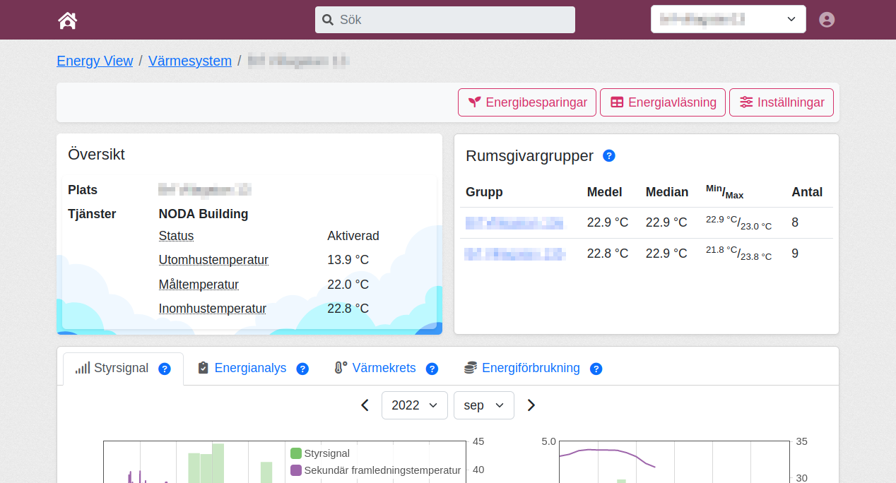
My Pages is a specific user portal for the NODA Building product, which helps property owners save energy and costs, achieve a more consistent indoor temperature, and enable the monitoring of the property's heat usage and indoor comfort over time.
The service is a cloud-based software that relies on data collection from the property and its substation to NODA's server. NODA uses the data to control heating more efficiently and to visualise the property's heat usage. Energy savings from the service are achieved by adjusting the heating of the radiator circuit inside the building to the actual needs of the property instead of just the outdoor temperature (the latter is the typical way to control heating in properties).
The system learns how the property uses energy by using room sensors for indoor temperature. By setting an indoor target temperature for the property, the service can control the heating towards this, thus avoiding unnecessary heating and maintaining a steady indoor temperature. The system also relies on weather forecasts to adjust the energy use to what is needed.
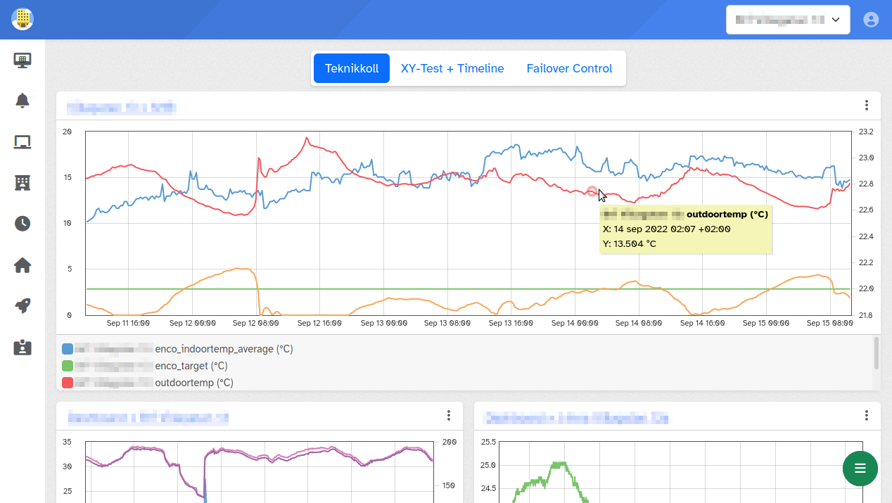
The user portal provides information based on the data collected from connected properties. It allows for monitoring indoor temperatures, viewing how much the service controls to optimise heating, observing energy use, and energy savings.
Introduction
My Pages is a specific user portal for the NODA Building product, which helps property owners save energy and costs, achieve a more consistent indoor temperature, and enable the monitoring of the property's heat usage and indoor comfort over time.
The service is a cloud-based software that relies on data collection from the property and its substation to NODA's server. NODA uses the data to control heating more efficiently and to visualise the property's heat usage. Energy savings from the service are achieved by adjusting the heating of the radiator circuit inside the building to the actual needs of the property instead of just the outdoor temperature (the latter is the typical way to control heating in properties).
The system learns how the property uses energy by using room sensors for indoor temperature. By setting an indoor target temperature for the property, the service can control the heating towards this, thus avoiding unnecessary heating and maintaining a steady indoor temperature. The system also relies on weather forecasts to adjust the energy use to what is needed.
The user portal provides information based on the data collected from connected properties. It allows for monitoring indoor temperatures, viewing how much the service controls to optimise heating, observing energy use, and energy savings.
Introduction
Introduction
API
Infrastructure introduction
The infrastructure required to run the NODA system is reasonably complex. It is no surprise that a complex system carries an inherently higher risk of exposure to attacks.
At the forefront of every design decision, NODA strives to mitigate the risk of such attacks.
Reliable, secure and encrypted communication channels are vital to achieving a secure environment.
But it's not the only item of importance.
Who has access, when they have access and why they have access are just as essential to prevent intrusion.
Devices in the field must never expose any ports to the internet. Instead, NODA solves the two-way communication by establishing a secure communication channel over MQTT to a managed service where each device has its own access rules.
Suppose the private certificate on a device, for whatever reason, is highjacked. Then, the device can easily be black-listed, and the certificate revoked to prevent further access.
Design in broad brush strokes
NODA aims to control energy equipment situated in the field. These devices are often located in the basement of buildings or inside smaller sheds in the vicinity.
By gathering vital data from these devices and crunching the numbers with machine learning algorithms, NODA achieves energy savings on a building level and also solves far more complex city-wide problems.
NODA provides equipment at the customer's site to communicate with many existing energy controllers. Often without the need to replace any existing hardware.
graph LR
    subgraph CustomerSite["Customer Site"]
    	Energy_Controller["Energy Controller"]
        NODA_Equipment["NODA Equipment"]
    end

    subgraph AnotherCustomerSite["Customer Site"]
        SCADASystem["SCADA System"]
        APIIntegration["NODA API Integration"]
    end

    subgraph NODA["NODA"]
        subgraph Kubernetes["Kubernetes"]
    		APIServer["APIServer"]
        	Computations["Machine Learning"]
        	MQTTBackend["MQTT Backend"]
        	UI["User Interface"]
    	end

		MQTTBridge["MQTT Bridge"]
    	Database[("Database")]
    end

    Person["User 🧑"]

	APIIntegration --> SCADASystem
	APIIntegration -->|"Internet 🔒"| APIServer

    NODA_Equipment --> Energy_Controller
    NODA_Equipment -->|"Internet 🔒"| MQTTBridge
    APIServer --> Database
    MQTTBridge <-->|"🔒"| MQTTBackend
    MQTTBackend --> Database
    Computations --> Database
    UI --> Database
    Person --> UI
On the server-side, NODA manages all of the ingress data, performs computations and solves optimization problems using both multi agent systems and machine learning.
Finally, the resulting control action signal is sent back to the controller over the internet.
Most of the data from these computations are then organized and presented so that it's practical and helps the customer in their daily work.
Development Process at NODA
At NODA, our roots in Software Engineering and Computer Science shape our approach to software development. As a company committed to excellence, we ensure that our development processes reflect our dedication to quality, collaboration, and innovation.
Collaboration and Transparency
We believe that transparency and collaboration are key to successful project delivery. Our development process is designed to be open and inclusive, ensuring that all stakeholders are kept informed and involved. By employing an iterative, community-like process, we maintain flexibility and adaptability, ensuring that our solutions meet the evolving landscape.
Embracing Free and Open Source Software
As a small company, we deeply appreciate the contributions of the Free Software and Open Source communities. While it is not always possible for us to contribute back directly, we encourage our employees to participate in and contribute to open source projects whenever possible. This not only helps the community but also enhances our team's skills and knowledge.
Development Process
Planning
Planning is the first step required for any development process. Given that most projects are based on a delivery date, we start with that and work backwards to ensure a comprehensive plan. This involves establishing:
-
Maintenance Period: Determining the duration for which the software will be maintained post-deployment.
-
Project Deadline: Setting the final delivery date for the project.
-
Testing Period: Allocating time for comprehensive testing to ensure the solution meets all requirements and quality standards.
-
Development Period: Scheduling the necessary time for the actual development work, including coding and initial testing.
-
Requirement Analysis Period: Defining the time needed for gathering, analyzing, and finalizing project requirements.
-
Resource Allocation: Identifying and assigning the necessary resources for both the development and maintenance phases.
For projects or solutions with ongoing development and evolving requirements, each addition of new features should be treated as a separate small or large project depending on the scope.
While this process may resemble the traditional Waterfall methodology, and in many respects it functions similarly, it is designed to ensure thoroughness before progressing to the next stage. This approach minimizes the risk of investing time and resources in work that may later prove unnecessary. However, unlike the rigid structure of Waterfall, our process is flexible and encourages back-stepping when necessary. This adaptability allows us to revisit and revise previous stages to ensure we are always working on the right tasks and meeting the project’s evolving needs.
Call it what you will; we simply don't put a label on it.
Requirement Analysis
At the outset, we focus on thoroughly understanding the needs and defining the project requirements. This involves:
-
Conducting requirement elicitation meetings with key personnel and stakeholders.
-
Performing research to determine the feasibility of the requirements.
-
Developing a project-specific Requirement Specification.
-
Engaging in negotiations to determine which requirements can be addressed and which cannot, often due to time constraints and resource availability.
The initial phase of requirement analysis concludes once all relevant parties have agreed on the specifications and the interpretation of each requirement.
Prototyping
Certain requirements may involve concepts or dependencies that fall outside the immediate expertise of the development team. To accurately assess the feasibility of these requirements, prototyping becomes essential. Prototyping allows us to explore, experiment, and gain the necessary knowledge to make informed decisions.
For example:
-
Integrating New Technologies: When a requirement involves using a new or unfamiliar technology, we create a prototype to test its compatibility and performance within our solution.
-
Complex User Interfaces: For most user interface designs, we develop prototypes to validate usability, functionality, and user experience.
-
System Interoperability: When the project requires integration with external systems or APIs, we prototype these connections to ensure smooth and reliable interactions.
-
Performance Testing: Prototypes can be used to test the system's performance under various conditions, identifying potential bottlenecks and optimization opportunities.
Prototyping helps us mitigate risks, validate assumptions, and refine our approach before full-scale development begins, ensuring a more efficient and effective development process.
Design
Based on the requirements outlined in the Requirement Specification, we design the system architecture, user interfaces, and other key components with security as a primary focus.
During the design phase, new requirements or adjustments to existing requirements may arise. As a result, we must remain flexible and revisit previous steps in the process to accommodate these necessary changes, often requiring a new iteration of Requirement Analysis.
Throughout the design phase, we will often produce:
-
System Architecture Diagrams: Detailed representations of the system's structure, including modules, data flow, and integration points.
-
User Interface Mockups: Visual prototypes of the user interfaces to ensure alignment with user experience goals and client expectations.
-
Database Schemas: Structured plans for data storage, ensuring efficient data management and retrieval.
-
Security Models: Plans addressing security measures to protect data integrity and privacy.
-
Technical Specifications: Documentation outlining the functionalities and interactions of each component, providing a clear blueprint for the development team.
Certainly! Here is the adjusted and extended version of the Testing chapter:
Testing
The concept of testing should precede the implementation phase. Even though there is nothing to test before code is written, sufficient information should be available for developers to prioritize testing from the outset. This approach shifts the traditional mindset of implementing first and testing later to a more proactive strategy of considering how to test functionality before implementing it, ensuring that the implementation is inherently testable.
Testing is conducted throughout the entire development phase and extends beyond it until we are satisfied with the quality assurance.
Artifacts from testing often include:
-
Unit Tests: Comprehensive tests for individual components, with a coverage target where less than 90% is unacceptable. These tests ensure each part of the codebase functions as intended.
-
Integration Tests: Tests to ensure that different modules and components work together seamlessly.
-
System Tests: End-to-end testing of the complete system to verify that it meets all specified requirements.
-
Performance Tests: Assessments to ensure the system performs well under various conditions and loads.
Development
During the development phase, code is written with testability and security as primary core pillars. Features are developed in separate branches, and once a feature is completed and passes all its tests, a merge request is created. A reviewer then examines the merge request, and if adjustments are necessary, the developer must make the modifications before the updated merge request is reviewed again. Once accepted, the code is merged into the main codebase. Each change is tracked using a versioning system (Git), allowing any state of the source code to be investigated.
If developers encounter issues that require changes to the Design or necessitate negotiations about the Requirements, these issues should be promptly raised with the responsible parties for each phase to find a solution.
Freeze
Once all features, or a limited set of features due to time constraints, have been merged into the main branch, a code freeze is implemented. During a freeze, no new features may be merged, and the current state of the main branch is assigned a tag. Development can continue in other branches, but the main branch is off-limits to ensure stability and focus on finalizing the current release. This period is used for final testing, bug fixes, and preparation for the release.
Only critical bugs may result in a slight thaw, where patches are merged to address these issues. Otherwise, the freeze remains in effect, ensuring the integrity and stability of the main branch until the release is complete.
During this time, the deployment team is notified about the upcoming release so they can schedule and prepare for the necessary work to deploy the solution into production.
Staging
Before deploying the solution, it undergoes testing in a staging environment. During this phase, a period of soak testing is conducted, where the system is used as if it were in a production environment. The duration of the soak testing period varies depending on the specific circumstances, and it is up to the testing team to determine the appropriate length of time required on a case by case basis.
Deployment
Once the testing team approves the contribution, the tagged release is assigned an appropriate version number and a build is pushed to the registry in the production environment. During the scheduled maintenance window, the deployment team pushes the update to the production system and monitors it for any unusual behavior for the next few hours. If any issues arise, a rollback to the previous version is performed.
Maintenance
Once the deployment team completes their work, the maintenance period begins. During this phase, automated logging mechanisms are in place to detect and report any unexpected behavior. These systems continuously monitor the application, ensuring that any issues are promptly identified and addressed.
Additionally, regular updates and patches are applied to maintain the system’s security and performance.
Software Lifecycle
We follow a structured process to ensure smooth software deployment. This process guides us through code commits, testing, deployment, and potential rollback, ensuring reliability and consistency throughout.
graph TD;
	ReportIssue[Report Issue]

    Start([Start]) --> A[Planning]
    A --> B[Requirement Analysis]
    B --> C[Prototyping]
    C --> D[Design]
    D --> E[Development]
    E --> F{Run Tests}
    F -->|Pass| G[Code Freeze]
    G --> Staging[Staging]
    Staging --> I[Tag Release]
    Staging -->|Major Issue|ReportIssue
    I --> J[Manual Building\nof Container]
    J --> K{Deploy to\nProduction}
    K -->|Success| L([Success])
    K -->|Fail| M[Revert to Previous\nVersion]
    M --> ReportIssue --> E
    F -->|Fail|E
    F -->|Major Issue|D
    D -->|Major Issue|B
Security of the infrastructure
%%{init: {'theme': 'base', 'themeVariables': { 'fontSize': '60px' }}}%%
graph TD
    Vest["🔒 🦺 🔑"]
Accounts
-
Never give personnel more access than strictly necessary to do their work.
-
Whenever possible, use automatic termination of accounts after a specific date or period.
Installation site
-
One should install hardware such as Modbus Gateway behind at least a locked door.
-
One must report missing hardware and its certificates revoked ASAP.
-
Equipment must be password protected with a unique random password.
-
Equipment must connect over an encrypted channel.
-
Equipment must never expose itself on the public internet.
-
Equipment must continuously be updated with security patches.
Office
-
Employees at NODA are required to use Bitwarden for password management.
-
TOTP is enforced whenever possible. For the most important objects, U2F security keys (from Yubico) are used.
-
Employees' workstations/laptops are full-disk encrypted.
-
Employees' workstations/laptops must be updated with new security patches at a regular interval.
-
WiFi passwords to the office network are never shared with visitors or friends.
Servers
-
Software that exposes an interface to another system must always require authentication, even if the system exposes an interface in a "secure" environment.
-
Access to the server system is only allowed through an SSH bastion using certificate authentication. Only the DevOps team has access to this gateway.
-
One must never expose the Kubernetes API to the internet outside a maintenance window. During these windows, only a handful of selected IP addresses are allowed to communicate with the API endpoint.
-
Machines, Container and Software packages must be tracked for updated of security patches.
Code
-
Code in repositories is continuously scanned for new security vulnerabilities.
-
Whenever an issue is found, the code is patched, verified and deployed within the next available maintenance window.
-
Employees are only given access to a project they are working on.
-
Code is written with security in mind.
-
As few dependencies on external systems as possible.
-
Known libraries shall ONLY ever manage cryptography. Never implement a crypto-solution by yourself.
-
Having test cases for most of the code is key to having a stable code base.
-
Transparency
Infrastructure
-
The NODA "Cloud" is hosted on AWS (Amazon Web Services) in the eu-north-1 region.
-
NODA uses DigitalOcean and Vultr for development and testing.
-
NODA uses Google Workspace.
-
NODA relies on FOSS (Free and Open Source) projects as part of the platform.
-
The platform is written in house, and is of our own design.
Work environment
-
NODA allows its employees to work from home.
-
Employees use Linux, FreeBSD, Windows and macOS in their workstations/laptops.
Software
-
NODA relies on several Open Source projects (to mention a few);
-
The software for the Modbus Gateway Addon is written using Arduino.
Open Source software licenses
NODA uses FOSS software with the following licenses;
- Apache License, Version 2.0
- BSD License 2, BSD License 3
- Eclipse Public License version 2.0
- GPLv2
- GPLv3
- LGPLv3
- MIT License
- Mozilla Public License 2.0 (MPL 2.0)
- Python License, Version 2
- PHP License, version 3.01
- Zope Public License 2.1
3rd-party solutions
Examples
Modbus Gateway Installation
A NODA Modbus Gateway can connect to any Modbus TCP or RTU capable energy controller. The NODA Modbus Gateway then reads and writes values to the energy controller using the Modbus protocol.
Installation complexity varies depending on the installation scenario;
- Freely programmable controller: Configurable Modbus layout and programmable logic.
- Application-specific controller: Static Modbus layout with only parameterise logic.
A freely programmable controller has to be configured to expose the required values. An application-specific controller seldom has the option to change the Modbus layout. Nor is it often possible to handle a failsafe mode directly in the controller using software logic.
An application-specific controller may contain this feature if the specific feature was part of the requirements when the controller was designed.
To solve this problem, NODA has developed the NODA Modbus Gateway Addon. A device that sits between the energy controller and the NODA Modbus Gateway and provides the missing logic required to handle situations when a connection to the internet fails for several hours or days.
graph TD
    subgraph clusterAWSIoT["AWS IoT"]
        IoT_Server["IoT Server"]
    end

    subgraph clusterSiteA["Customer Site"]
        Modbus_Gateway["Modbus Gateway"]
        Modbus_Gateway_Addon["Modbus Gateway Addon\n(optional)"]
        Energy_Controller["Energy Controller"]
    end

    Modbus_Gateway -->| | Modbus_Gateway_Addon
    Modbus_Gateway_Addon -->| | Energy_Controller
    Modbus_Gateway -->|"🔒"| IoT_Server
The NODA Modbus Gateway connect to the secure endpoint on AWS IoT. Data is then forwarded to the NODA system and handled by various processes. The system crunches the numbers and sends control signals back the controller via AWS IoT and the NODA Modbus Gateway.
Finally, a customer connects to the EnergyView (or My Pages) system to browse the data at their heart's content.
graph LR
    subgraph clusterNodaPrivate["Noda Private"]
        DBMS[("DBMS")]
        Mosquitto["Mosquitto"]
    end

    subgraph clusterNodaPublic["Noda Public"]
        EnergyView["EnergyView"]
        Mosquitto["Mosquitto"]
    end

    subgraph clusterAWSIoT["AWS IoT"]
        IoT_Server["IoT Server"]
    end

    subgraph clusterSiteA["Customer Site"]
        Modbus_Gateway["Modbus Gateway"]
    end

    Mosquitto -->| | DBMS
    EnergyView -->| | DBMS
    IoT_Server -->|"🔒"| Mosquitto
    Modbus_Gateway -->|"🔒"| IoT_Server

    Customer["💻 Customer"]
    Customer -->|"🔒"| EnergyView
Indoor Sensors Installation
There are several ways to get indoor sensor data into the NODA system.
The most common way is for equipment in the field to send data to NODA. This can be either via Wireless M-Bus gateways or via MQTT or HTTP from a gateway connected to a LoRa network.
These devices are often provisioned once and usually work for several years without intervention.
graph LR
    subgraph clusterNodaPrivate["Noda Private"]
        DBMS[("DBMS")]
    end

    subgraph clusterNodaPublic["Noda Public"]
        EnergyView["EnergyView"] -->| | DBMS
        W_MBus["W-MBus"] -->| | DBMS
    end

    subgraph clusterSite["Customer Site"]
        Indoor_Sensors["🌡️ Indoor Sensors"]
        Indoor_Sensors -->|"🔒"| W_MBus
    end

    Customer["💻 Customer"]
    Customer -->|"🔒"| EnergyView
Typical logging intervals are between 5 and 15 minutes, depending on expected lifespan, technology and so forth. Once the data has landed in the NODA system it can be viewed by customers using either EnergyView or My Pages.
3rd Party Integration Installation
While not very common, NODA allows for customer specific intergrations. This is often solved by using the NODA EnergyView API or the NODA Self-host API.
graph LR
    subgraph clusterNodaPrivate["Noda Private"]
        DBMS[("DBMS")]
    end

    subgraph clusterNodaPublic["Noda Public"]
        EnergyView["EnergyView"] -->| | DBMS
    end

    subgraph clusterSiteC["Customer Site"]
        Third_Party_Solution["3rd party solution"] -->|"🔒"| EnergyView
    end

    Customer["💻 Customer"]
    Customer -->|"🔒"| EnergyView
IEC Installation
NOTICE: This solution reaches end of life (EOL) on the 31st of December 2022.
The NODA IEC is a solution built in-house by NODA. It sits between an outdoor sensor (RTD) and the energy controller. The IEC measures the resistance of the outdoor sensors, converts it to a temperature, applies an offset (or not) and converts the new temperature back to a resistance value for the controller.
This solution has both benefits and drawbacks. Using this method, one can not control specific circuits in a building unless there is one controller for each circuit. In addition, everything affected by the outdoor temperature will be affected by an offset.
However, it's a simple concept and works well if used in the right circumstances.
graph LR
    subgraph clusterNodaPrivate["Noda Private"]
        DBMS[("DBMS")]
    end

    subgraph clusterNodaPublic["Noda Public"]
        EnergyView["EnergyView"]
        IEC_Sync["IEC Sync"]
    end

    subgraph clusterSiteA["Customer Site"]
        IEC["IEC"]
    end

    EnergyView -->| | DBMS
    IEC_Sync -->| | DBMS
    IEC -->|"🔒"| IEC_Sync

    Customer["💻 Customer"]
    Customer -->|"🔒"| EnergyView
Since the IEC cannot query an energy controller for measured values, these are collected by installing surface-mounted 1-wire temperature sensors on the essential circuits.
Important usage and safety information
The following safety precautions must be observed during all phases of the operation, usage, service or repair of any NODA product.
Users of the product are advised to convey the following safety information to users and operating personnel and to incorporate these guidelines into all manuals supplied with the product. Failure to comply with these precautions violates safety standards of design, manufacture and intended use of the product.
NODA Intelligent Systems AB assumes no liability for customer’s failure to comply with these precautions.
The products are developed for indoor use only, unless clearly stated otherwize.
The installation of the product should be performed by a qualified electrician or another professional with the required knowledge. It is important to follow all safety information of this manual when installing the product.
Make sure to read this manual carefully and follow it step by step to ensure a secure usage and to get the most out of your product.
Mobile router introduction
Communication with equipment in the field can be solved using various solutions. Choosing one of these solutions always boils down to weighing functionality vs cost.
Using a customer's existing infrastructure to communicate with the internet is always a problem. Especially so, if the customer is unfamiliar with their own infrastructure.
As a result, NODA decided to go with a mobile router solution. A device which, on its own, connects to the internet via the 4G or 5G mobile network. Then, this mobile router connects to the energy controller (A regulator or similar device) via Modbus over either TCP or RTU.
All of this is secured by exchanging data over an encrypted MQTT connection.
NODA requires this level of interaction with the energy controller to get all required measurement values, along with the ability to modify control parameters. This way, the controller can go about its business doing what it's good at, controlling. Whilst being nudged in the right direction by the analytic processes provided by NODA.
Hardware options
NODA relies on hardware from the manufacturer Teltonika.
The router we use and support are;
The RUT240 is primarily used as a Mobile router for wired ethernet devices, while the RUT950 and RUT955 series are mainly used as Modbus Gateway.
Remote management
An essential function of equipment deployed in the field is accessing these devices securely.
Devices such as routers always require software upgrades or maintenance to fix newly discovered security vulnerabilities.
Often this requires a VPN solution at the customer site. Or that each router connects as a client to a central management system using VPN.
The should be no situations where equipment is directly exposed to the internet. Such a solution is fraught with troubles down the line.
The NODA routers provided by Teltonika solve this problem by providing a secure connection using secured MQTT as a transport layer. The device connects to Teltonikas Remote Management System (RMS), where all devices are accessible and easily managed.
Introduction
NODA Modbus Gateway provides a reliable Modbus TCP master/slave solution where data transmits over a secure MQTT connection.
The Modbus Gateway acts as a Modbus TCP or RTU master/slave. It can communicate with any Modbus TCP slave connected via the LAN interface or act as a Modbus TCP slave. It can also communicate with any Modbus RTU slave connected via an RS-485.
Data is transmitted over the mobile network using a 4G or 5G modem internal to the gateway. The LAN interface or the RS-485 bus is not used to transfer outbound data to NODA. Only the WLAN connection via Wired Ethernet or Mobile Internet can access the internet.
For a list of limitations concerning the installation, see the details in Modbus support.
Compatibility requirements
For a list of known compatible devices, take a look at Manufacturer templates.
General requirements
A typical installation requires the ability to READ the following tags/values;
- Outdoor temperature
- Primary side flow (supply) temperature
- Primary side return temperature
- Primary side flow (supply) volume
- Primary side volume
- Primary side heat energy
- Primary side heat power
- Secondary side #1 flow temperature
- Secondary side #1 return temperature
- Current secondary side supply temperature
NOTE: If additional secondary side loops exist, they can also be included.
Along with the ability to WRITE the following tags/values;
- Secondary side supply temperature offset
or
- Forced secondary side supply temperature
Whichever depends on the limitations of the Modbus slave and the control system behind it.
NOTE: Specific use cases may require situation-specific solutions. In such a case, don't hesitate to get in touch with NODA for further support.
Components
The NODA Modbus Gateway consists of;
- Teltonika Mobile Router
- Antennas
- Power Supply Unit
- SIM-card (may be omitted)
- Modbus Gateway Addon (required for certain energy controllers)
Teltonika Hardware options
There are two different hardware options available;
RUT950/RUT951
The RUT950 and RUT951 are 4G routers. They come with 3 LAN (Ethernet) ports and 1 WAN (Ethernet) port. This option is well suited for use with freely programmable energy controllers with support for Modbus TCP.
RUT955/RUT956
The RUT955 and RUT956 are 4G routers. They come with 3 LAN (Ethernet) ports and 1 WAN (Ethernet) port; they also have 1 RS-485 port and 1 RS-232 port, along with a few generic I/O ports. This option is well suited for use with freely programmable energy controllers with support for Modbus TCP or Modbus RTU.
Introduction
The NODA Modbus Gateway Addon acts as a tiny external brain-aid for application-specific energy controllers.
Whenever a controller cannot handle the logic required to return to zero from an affected state, this solution is needed to restore the default state on the controller.
For example, if an offset of the supply temperature on the secondary side is 6.5 degrees Celsius and the internet connection goes down. Then, the controller will happily continue with the same 6.5 degrees offset until internet connectivity is restored. For a worst-case scenario, this can take several days.
This addon's sole purpose is to add logic to the energy controller without putting it in the environment of an operating system that is frankly less stable than a microcontroller's.
Components
The hardware we choose, 10 I/O's Digital Module is made by the Spanish company; Boot and Work Corp S.L. (Industrial Shields).
The hardware is built around an ESP32 and supports the Arduino Development Environment.
In the future, we aim to support several off-the-shelf Arduino-compatible products from different manufacturers.
Communication
The NODA Modbus Gateway Addon can communicate with Modbus devices over either Modbus TCP (Ethernet) or Modbus RTU (RS-485).
The solution uses the same protocol over MQTT as the NODA Modbus Gateway.
Modbus TCP
Communication with any Modbus TCP compatible Modbus Slave is possible over any port.
See the Setup section for more details about configuring the Modbus TCP support.
Modbus RTU
The communication protocol does not support specifying an RS-485 target. Instead, only IP targets are supported.
To get around this limitation, the NODA Modbus Gateway Addon assigns special meaning to the IPv4 loopback addresses. The loopback address of 127.1.1.1 is used as a way to forward a request to the RS-485 interface. The TCP port (typically 502) is silently ignored in such a request.
See the Setup section for more details about how to configure the RS-485 support.
Setup of Modbus Gateway Addon
Once powered on, the Addon will either request an IP address via DHCP or use the static IP configured via the user-interface.
When connected to a NODA Modbus Gateway, the Addon device will be assigned the IP 192.168.1.100.
Access the user-interface by entering the following in a web-browser; http://192.168.1.100.
It's is highly recommended to access this page in "incognito" or "private window" to avoid issues with password caching.
Login
The username is admin.
The password is unique for each device and can be requested from NODA.
Configuration
The following parameters can be changed.
Network
- MAC address: The MAC address can be changed here if required.
- Static IP: Assigning a static IP will disable DHCP. An empty field will active DHCP.
- Static DNS: Required if static IP is used.
- Static subnet: Required if static IP is used. On the form
255.255.255.255.
RS485 (for Modbus RTU)
- Baudrate: The speed over the RS-485 network. All devices must use the same speed.
- Mode: e.g. 8N1 or 7E1 etc.
MQTT
- ClientID: Identifier used when connecting to an MQTT broker.
- Host: The IP of the MQTT broker.
- Port: The TCP port of the MQTT broker.
- Username: Optional username used to connect to the MQTT broker.
- Password: Optional password used to connect to the MQTT broker.
Failover
- Communication timeout: The number of seconds without any data over MQTT, after which the device switches to failover state.
- On communication error: A list of instruction to execute when switching to a failover state. These instructions are used to clear any offset and return the energy controller to a clean-state.
Password
- WebUI Password: Used to change the password of the Web-UI.
Modbus support
Since Modbus was designed in the late 1970s to communicate to programmable logic controllers, the number of data types is limited to those understood by PLCs at the time. Therefore, large binary objects are not supported.
No standard way exists for a master device to find the description of a data object, for example, to determine whether a register value represents a temperature between 25 and 98 degrees Celsius.
Therefore the mapping and structure of the data have to be established for successful interoperability, as a client may store values not only in a single register but in several adjacent holding registers.
Limitations in the protocol support
As of this writing, the software used by NODA to achive communication with energy control equipment via Modbus over MQTT, is limited to the support implemented by Teltonika in their equipment.
This limits the available commands to send over Modbus to only Write Single Holding Register (6), Write Multiple Holding Registers (16) and Read Holding Registers (3). There is thus currently no support for reading and writing to coils and reading discrete inputs.
Single holding register data types
- 8 Bit Unsigned Integer (uint8)
- 8 Bit Signed Integer (int8)
- 16 Bit Unsigned Integer (uint16)
- 16 Bit Signed Integer (int16)
- 16 Bit Float (float16)
Multi (2) holding registers data types
- 32 Bit Unsigned Integer (uint32)
- 32 Bit Signed Integer (int32)
- 32 Bit Float (float32)
Both Word and Byte order can be Little- or Big Endian. But the order has to be consistent throughout.
NOTE: While NODA Modbus Gateway supports the above data types, your specific target slave device might not be able to handle them. Please refer to the manual for the slave device for details.
RS-485 limitations
The RS-485 driver can drive a maximum of 32 receivers, provided that the receiver input impedance is 12 k$\Omega$. If receiver impedances are higher, the maximum number of receivers in the network increases. Any combination of receiver types can be connected, provided their parallel impedance does not exceed $Rload > 375 \Omega$.
Solution for complete protocol support
To get around the current limitations in the Teltonika router, NODA implemented a separate solution with the capability of acting as an alternative to the Teltonika software in their router. This solution still requires Teltonika router to access the internet in a secure way. For more details about this solution take a look at the Modbus Gateway Addon
Recommendations
Depending on the usage scenario, limitations or flexibilities in the Modbus TCP slave, the data mapping will vary. Therefore, the following mapping is only the prefered mapping by NODA. As such, it can be changed in agreement with NODA to match the specific situation.
Modbus mapping for a typical building
Word Order: Big Endian
Byte Order: Little Endian
| Order | Value name | Encoding | Amplification | Unit | Direction | Function Code |
|---|---|---|---|---|---|---|
| 1 | Outdoortemp | uint16 | 1/100 | Celcius | Read | 3 |
| 2 | Outdoortemp Offset | uint16 | 1/100 | Kelvin | Write | 6 |
| 3 | Primary Flow (Supply) Temperature | int16 | 1/100 | Celcius | Read | 3 |
| 4 | Primary Return Temperature | int16 | 1/100 | Celcius | Read | 3 |
| 5 | Primary Flow Volume | int16 | 1/10* | l/h* | Read | 3 |
| 6 | Primary Side Volume | int16 | 1/10* | m3* | Read | 3 |
| 7 | Primary Heat Energy | int16 | 1/10* | MWh* | Read | 3 |
| 8 | Primary Heat Power | int16 | 1/10* | kW* | Read | 3 |
| 9 | Secondary Side (#1) Flow | int16 | 1/100 | Celcius | Read | 3 |
| 10 | Secondary Side (#1) Return | int16 | 1/100 | Celcius | Read | 3 |
| 11 | Secondary Side (#2) Flow | int16 | 1/100 | Celcius | Read | 3 |
| 12 | Secondary Side (#2) Return | int16 | 1/100 | Celcius | Read | 3 |
| ... | ... | ... | ... | ... | ... | ... |
| XX | Secondary Side (#n) Flow | int16 | 1/100 | Celcius | Read | 3 |
| XX | Secondary Side (#n) Return | int16 | 1/100 | Celcius | Read | 3 |
* Depends on specific circumstances
The structure outlined in the table can repeat if the Modbus TCP slave interfaces with several regulators and or control points.
NOTE: If additional secondary side circuits exist, they should be included.
NOTE: Holding register numbers are intentionally not outlined as they likely will vary from one Modbus TCP slave to another.
Installation preparation
The NODA Modbus Gateway comes prepared with all necessary certificates to connect to the NODA MQTT network securely.
Modbus TCP
For access to the Modbus TCP slave(s) or acting as a Modbus TCP slave itself. The NODA Modbus Gateway will need either a static or dynamic (DHCP) IP assigned to it in the LAN.
Don't hesitate to contact the network administrator as this information is only known to, and can be handled by, the network administrator. Once an IP number is assigned to the NODA Modbus Gateway, either via static or dynamic assignment, these details should be communicated to NODA, as they are required for device setup on the LAN.
NOTE: If the network administrator requests a MAC address. This address is labelled as LAN MAC on the underside of the NODA Modbus Gateway. If the label is missing or has been damaged, please get in touch with NODA for help.
Modbus RTU
To access Modbus RTU slave(s), the NODA Modbus Gateway will need access to an RS-485 network. Details on how an RS-485 network works are out of scope for this document.
To access Modbus RTU slave(s), the RS-485 bus configuration is required.
Default values are highlighted in bold.
- Baud rate (300, 1200, 2400, 4800, 9600, 19200, 38400, 57600 or 115200)
- Parity bits (none, odd, even)
- Stop bits (1, 2)
- Flow Control: (None, Xon/Xoff)
- Slave id or range of slave ids: (1-247)
Installation
The supplied DIN rail mount is the recommended way to mount the NODA Modbus Gateway. This may be in any larger installation cabinet, smaller installation box or similar. If the equipment is safe from water damage and dust ingress, it can be mounted without a separate enclosure as a last resort.
- Estimation of time required for installation
- Mounting location
- Configuration of the NODA Modbus Gateway
- Power supply
- Ethernet
- RS-485
- Wiring
- Setup
Estimation of time required for installation
The time required depends on a few factors;
- Familiarity with previous installations of NODA Modbus Gateway equipment.
- Familiarity with the control equipment.
- Knowledge of connecting Ethernet networks or RS485-bus networks.
- If the controller is freely programmable or an application-specific controller.
The tasks required for installation are (in general);
- Contact NODA and make a plan for installation a few days ahead of time
- Get to the installation location
- Find the energy controller
- Ensure that one can manage the controller over Modbus TCP / RTU
- Locate a suitable mounting location for the NODA Modbus Gateway
- Mount the equipment
- Wire the controller and NODA Modbus Gateway equipment together
- Configure the controller (often only required for freely programmable controllers)
- Validate the installation with NODA deployment staff
A skilled technician can perform these tasks in less than four hours without taking into account time for getting to the location, establishing a work environment and clean-up.
Mounting location
The NODA Modbus Gateway connects to the NODA MQTT network via the mobile network (4G / 5G). Therefore, install the device in a location where wireless transmission is allowed and the appliance can acquire a wireless signal.
Inside a larger installation cabinett
This option is one of the most well-suited installation locations. The equipment is safe from the environment, and if the cabinet is locked also secured from unauthorized access. Remember that the cabinet may work as a signal shield against the mobile network, resulting in a very low or no signal for the NODA Modbus Gateway. In this situation, your only option is to exchange the included antennas for antennas with an extension cord.
Inside a separate plastic box / enclosure
Another suitable choice is to use a larger box with a DIN rail to mount the NODA Modbus Gateway and the power supply. This box can be placed upwards to 50 meters from the controller if one can find no suitable location in the vicinity.
Without a protective enclose
As a last resort, one can mount the NODA Modbus Gateway directly on any suitable surface as long as the risk of water or dust ingress is low.
Configuration of the NODA Modbus Gateway
Configuration of the NODA Modbus Gateway is done remotely by NODA deployment staff. Depending on the installation scenario and the prep work done.
This configuration can often be done ahead of the shipment of the equipment. If any equipment configuration is required in the field, then once the equipment is connected to the internet, it can be accessed by the NODA deployment staff.
Power supply
The NODA Modbus Gateway is powered by the supplied power supply or any 9-30V industrial power supply.

Ethernet
When acting as a Modbus master, the NODA Modbus Gateway will connect to the network (LAN) via a switch from the ethernet port marked LAN1. However, suppose the slave device is not already on a LAN. In that case, one can directly connect the device to the NODA Modbus Gateway on the ethernet port marked LAN1 or the next available LAN port if used in conjunction with a NODA Modbus Gateway Addon.

When acting as a Modbus slave, the NODA Modbus Gateway will provide a Modbus TCP interface with a defined Holding Register scope on the LAN1 port. The default port number for this is 502.
RS-485
Wire the NODA Modbus Gateway to the network by using the following pinout.

4-wire network
If the NODA Modbus Gateway is wired to a 4-wire network (separate request and reply buses), then wire the D_P pin and the D_N pin to the request bus and wire the R_P pin and the R_N pin to the reply bus.
2-wire network
If the NODA Modbus Gateway is wired to a 2-wire network (single request and reply bus), bridge the pin D_P to the R_P pin and the D_N pin to the R_N pin before connecting to the bus.
Wiring
Modbus Gateway without Addon
Installation without the NODA Modbus Gateway Addon only works if the energy controller can be programmed (freely programmable controller). If the controller is an application-specific controller, then the NODA Modbus Gateway Addon is required.
Connect the energy controller to the NODA Modbus Gateway using either; Ethernet or RS-485.
Modbus Gateway with Addon
If you are using a NODA Modbus Gateway Addon, then see details in Addon > Wiring.
Setup
Once installed and up and running. The NODA Modbus Gateway should be visible in Teltonika RMS. Suppose you don't have access to this tool. Then contact NODA support for acknowledgement.
When a connection to Teltonika RMS has been established, you can continue with the Setup step.
Setup
Further network setup (see the Preparation section) is done remotely by NODA personnel via a remote management system once the NODA Modbus Gateway has successfully connected to the internet via the mobile network.
NOTE: For highly skilled technicians, if required, NODA can provide temporary access to the web interface of the NODA Modbus Gateway.
Slave device setup
The Modbus TCP/RTU slave device should be configured by a professional with the required knowledge of the specific equipment. Specifics on this task is out of scope for this document. Please refer to the technical manual for the particular slave device.
TCP Gateway setup
Ethernet Network
The default IP on the LAN interface for the NODA Modbus Gateway is 192.168.1.1. However, one can change the IP if the network requires it.
Ethernet Firewall
Suppose an optional and appropriately recommended firewall limits the communication between NODA Modbus Gateway and the Modbus TCP slave(s). In that case, the recommended solution is to port-forward the traffic over the firewall from the NODA Modbus Gateway and on to the target Modbus TCP slave on the LAN.
Such configuration is out of the scope of this document and should generally be handled by a network administrator.
RTU Gateway setup
If the settings for the RS-485 port matches the RS-485 network, there should be no further setup necessary.
Server-side request setup
Data exchange setup between the NODA Modbus Gateway and the Modbus TCP slave(s) is done via the online tool EnergyView, using administrative credentials. This step is out of scope for this document.
For help and more information on this, don't hesitate to get in touch with NODA.
Templates
NOTE: This list contains verified controllers. New controllers are added continuously and most Modbus controllers are compatible.
Please contact NODA if have any questions or if your controller is not listed.
Each energy controller is often unique in its particular, unique way. Still, manufacturers often retain the same patterns and layout throughout their offerings.
This section provides a verified list of required Modbus values in a controller to allow full functionality of the NODA Modbus Gateway.
Each template contains a details explanation of how to handle that specific controller.
Supported manufacturers
Select a manufacturer to get a list of supported controllers and mapping.
Controllers from other manufacturers
Any controller capable of acting as a Modbus TCP or Modbus RTU slave/server can likely be handled by our Modbus Gateway.
Any integration outside of what we support requires work and knowledge of the controller. Something we can't manage for all available controllers on the market.
Please read the Compatibility section for more details on determining the possibility of support for your specific controller.
If you have additional questions, please contact NODA.
Abelko controllers
https://abelko.se/produkter/
More documentation coming soon. :)
Bastec controllers
Integration with a Bastec controller is over Modbus TCP (Ethernet). The preferred setup is to use a NODA Modbus Gateway as a Modbus Slave.
The Bastec controller is freely programmable.
Table of Content
BAS2 XE16
| Model | Supported | Details |
|---|---|---|
| BAS2 XE16-LT | ❌ No | Missing Modbus support |
| BAS2 XE16-COM | ✅ Yes | See details here. |
| BAS2 XE16-COM V2 | ✅ Yes | See details here. |
BAS2 XL13
Modbus values
Using the following layout, at most four (4) heating systems are supported.
Scaling of integer values
Scale (factor) is used to transform a decimal value into an integer value by multiplying it with that value. This is often required as simple computers are often bad at handling decimal values. As a result, we lose the decimal part when converting a decimal value to an integer value.
For example, if the value 3.1415 is to be managed in such a way, it can be scaled using 10, 100, 1000 or even 10000. Giving us the integer values; 31, 314, 3141 or 31415.
These integer values can then be transmitted to a more intelligent computer, where they are divided by the same factor to produce a decimal value once more.
Remember that the scale factor decides how many decimals are retained once converted back to a decimal value.
Outdoor sensors
The following values are available as Holding Registers.
| Modbus Number | Size | Scale | Description |
|---|---|---|---|
| 1200 | 1 | 100 | Outdoor temperature HS1 |
| 1300 | 1 | 100 | Outdoor temperature HS2 |
| 1400 | 1 | 100 | Outdoor temperature HS3 |
| 1500 | 1 | 100 | Outdoor temperature HS4 |
Supply and Return temperature
The following values are available as Holding Registers.
| Modbus Number | Size | Scale | Description |
|---|---|---|---|
| 1201 | 1 | 100 | Supply temperature HS1 |
| 1202 | 1 | 100 | Return temperature HS1 |
| 1301 | 1 | 100 | Supply temperature HS2 |
| 1302 | 1 | 100 | Return temperature HS2 |
| 1401 | 1 | 100 | Supply temperature HS3 |
| 1402 | 1 | 100 | Return temperature HS3 |
| 1501 | 1 | 100 | Supply temperature HS4 |
| 1502 | 1 | 100 | Return temperature HS4 |
Calculated supply temperature
The following values are available as Holding Registers.
| Modbus Number | Size | Scale | Description |
|---|---|---|---|
| 1203 | 1 | 100 | Calculated supply setpoint HS1 |
| 1303 | 1 | 100 | Calculated supply setpoint HS2 |
| 1403 | 1 | 100 | Calculated supply setpoint HS3 |
| 1503 | 1 | 100 | Calculated supply setpoint HS4 |
M-Bus Heat Meter
The following values are available as Holding Registers.
All M-Bus values are 32-bit wide and takes up two Holding Registers. They are organized in order as High Word and then Low Word.
| Modbus Number | Size | Scale | Description |
|---|---|---|---|
| 1210 | 2 | 1000 | Energy, Heat Meter HS1 (MWh) |
| 1212 | 2 | 10 | Power, Heat Meter HS1 (kW) |
| 1214 | 2 | 1 | Flow, Heat Meter HS1 (l/h) |
| 1216 | 2 | 1 | Supply temperature, Heat Meter HS1 (C) |
| 1218 | 2 | 1 | Return temperature, Heat Meter HS1 (C) |
| 1220 | 2 | 100 | Volume, Heat Meter HS1 (m3) |
| 1310 | 2 | 1000 | Energy, Heat Meter HS2 (MWh) |
| 1312 | 2 | 10 | Power, Heat Meter HS2 (kW) |
| 1314 | 2 | 1 | Flow, Heat Meter HS2 (l/h) |
| 1316 | 2 | 1 | Supply temperature, Heat Meter HS2 (C) |
| 1318 | 2 | 1 | Return temperature, Heat Meter HS2 (C) |
| 1320 | 2 | 100 | Volume, Heat Meter HS2 (m3) |
| 1410 | 2 | 1000 | Energy, Heat Meter HS3 (MWh) |
| 1412 | 2 | 10 | Power, Heat Meter HS3 (kW) |
| 1414 | 2 | 1 | Flow, Heat Meter HS3 (l/h) |
| 1416 | 2 | 1 | Supply temperature, Heat Meter HS3 (C) |
| 1418 | 2 | 1 | Return temperature, Heat Meter HS3 (C) |
| 1420 | 2 | 100 | Volume, Heat Meter HS3 (m3) |
| 1510 | 2 | 1000 | Energy, Heat Meter HS4 (MWh) |
| 1512 | 2 | 10 | Power, Heat Meter HS4 (kW) |
| 1514 | 2 | 1 | Flow, Heat Meter HS4 (l/h) |
| 1516 | 2 | 1 | Supply temperature, Heat Meter HS4 (C) |
| 1518 | 2 | 1 | Return temperature, Heat Meter HS4 (C) |
| 1520 | 2 | 100 | Volume, Heat Meter HS4 (m3) |
Offset of supply temperature
The following values are available as Holding Registers.
| Modbus Number | Size | Scale | Description |
|---|---|---|---|
| 1230 | 1 | 100 | Parallel transfer of setpoint-curve HS1 |
| 1330 | 1 | 100 | Parallel transfer of setpoint-curve HS2 |
| 1430 | 1 | 100 | Parallel transfer of setpoint-curve HS3 |
| 1530 | 1 | 100 | Parallel transfer of setpoint-curve HS4 |
Watchdog / Failover
The following values are available as Holding Registers.
| Modbus Number | Size | Scale | Description |
|---|---|---|---|
| 1290 | 1 | 1 | Watchdog counter |
There is only one (1) watchdog counter, and that is for the first HS. All related logic should use the same counter as a way to determine that any offset done to the system is a frozen value.
Suppose the counter hasn't changed in 30 minutes. The controller should reset the "Offset of supply temperature" to zero (0). The controller should automatically re-activate the offset when the counter starts working again.
Installation
Installation requires a NODA Modbus Gateway.
Installation steps can be found under Modbus Gateway > Installation.
Setup
Before performing this step. Please ensure that you have finished all necessary steps in Modbus Gateway > Installation.
To complete the following steps, administrative access to NODA EnergyView is required. If you do not have administrative access to NODA EnergyView then setup has to be carried out by NODA support personell.
For each heating system controlled, NODA requires the following;
- Outdoor sensors (C)
- Supply and return temperature (C)
- Offset of supply temperature (K)
- M-Bus Heat Meter values
- Supply and return temperature (C)
- Energy (MWh)
- Power (kW)
- Volume (m3)
- Flow (l/h)
- Calculated supply temperature (C)
M-Bus Heat Meter values may be omitted if these values are transferred to NODA's system in some other way than via the Bastec controller.
Roles
- The NODA Modbus Gateway acts as a Modbus Slave.
- The Bastec controller acts as a Modbus Master.
Recommended mapping for integration
The following mapping is a recommended example of a single heating system installation. However, extend the mapping accordingly if there is more than one heating system.
Holding registers
| Modbus Number | Value type | Multiplication | Direction | Sensor target |
|---|---|---|---|---|
| 1200 | 16 bit signed integer | 0.01 | GET | outdoortemp (C) |
| 1201 | 16 bit signed integer | 0.01 | GET | supplytemp_sec (C) |
| 1202 | 16 bit signed integer | 0.01 | GET | returntemp_sec (C) |
| 1203 | 16 bit signed integer | 0.01 | GET | supplytemp_sec_controller_setvalue (K) |
| 1210 | 32 bit signed integer | 0.001 | GET | meter_heatenergy (MWh) |
| 1212 | 32 bit signed integer | 0.1 | GET | meter_effect (kW) |
| 1214 | 32 bit signed integer | 1 | GET | meter_volumeflow (l/h) |
| 1216 | 32 bit signed integer | 1 | GET | meter_primsupplytemp (C) |
| 1218 | 32 bit signed integer | 1 | GET | meter_primreturntemp (C) |
| 1220 | 32 bit signed integer | 0.01 | GET | meter_volume (m3) |
Holding registers
| Modbus Number | Value type | Multiplication | Direction | Sensor target |
|---|---|---|---|---|
| 1230 | 16 bit signed integer | 100 | SET | supplytemp_sec_offset (C) |
| 1290 | 16 bit signed integer | 1 | SET | watchdog (number) |
Danfoss controllers
Integration with a Danfoss controller is over Modbus TCP (Ethernet) or Modbus RTU (RS-485). The NODA Modbus Gateway as a Modbus Client/Master and the Danfoss controller acts as a Server/Slave.
The Danfoss controller is application-specific and requires separate Application Key for different scenarios.
| Model | Supported | Details |
|---|---|---|
| ECL Comfort 110 | ❌ No | |
| ECL Comfort 210 | ✅ Yes | See details here. |
| ECL Comfort 296 | ✅ Yes | See details here. |
| ECL Comfort 310 | ✅ Yes | See details here. |
Danfoss ECL210/296/310 Applications
A2XX applications
A3XX applications
P3XX applications
P5XX applications
Danfoss ECL210/296/310 Application A207
This application contains 1 variant(s)
Table of Content
Application A207.1
Example A

Danfoss ECL210/296/310 Application A214
This application contains 6 variant(s)
Table of Content
- Application A214.1
- Application A214.2
- Application A214.3
- Application A214.4
- Application A214.5
- Application A214.6
Application A214.1
Example A

Example B

Example C

Example D

Example E

Application A214.2
Example A

Example B

Application A214.3
Example A

Example B

Application A214.4
Example A

Example B

Application A214.5
Example A

Example B

Example C

Application A214.6
Example A

Example B

Danfoss ECL210/296/310 Application A217
This application contains 3 variant(s)
Table of Content
Application A217.1
Example A

Example B

Example C

Example D

Example E

Application A217.2
Example A

Example B

Application A217.3
Example A

Example B

Example C

Example D

Danfoss ECL210/296/310 Application A230
This application contains 5 variant(s)
Table of Content
Application A230.1
Example A

Example B

Example C

Example D

Application A230.2
Example A

Example B

Example C

Example D

Application A230.3
Example A

Example B

Example C

Example D

Application A230.4
Example A

Example B

Example C

Example D

Application A230.5
Example A

Danfoss ECL210/296/310 Application A231
This application contains 2 variant(s)
Table of Content
Application A231.1
Example A

Application A231.2
Example A

Danfoss ECL210/296/310 Application A232
This application contains 1 variant(s)
Table of Content
Application A232.1
Example A

Example B

Example C

Example D

Example E

Example F

Danfoss ECL210/296/310 Application A237
This application contains 2 variant(s)
Table of Content
Application A237.1
Example A

Example B

Example C

Example D

Application A237.2
Example A

Example B

Danfoss ECL210/296/310 Application A247
This application contains 3 variant(s)
Table of Content
Application A247.1
Example A

Example B

Example C

Application A247.2
Example A

Example B

Example C

Application A247.3
Example A

Example B

Example C

Danfoss ECL210/296/310 Application A260
This application contains 1 variant(s)
Table of Content
Application A260.1
Example A

Example B

Example C

Example D

Example E

Example F

Danfoss ECL210/296/310 Application A266
This application contains 3 variant(s)
Table of Content
Application A266.1
Example A

Example B

Example C

Application A266.2
Example A

Application A266.9
Example A

Danfoss ECL210/296/310 Application A267
This application contains 1 variant(s)
Table of Content
Application A267.1
Example A

Example B

Example C

Example D

Example E

Danfoss ECL210/296/310 Application A275
This application contains 3 variant(s)
Table of Content
Application A275.1
Example A

Example B

Application A275.2
Example A

Example B

Example C

Example D

Application A275.3
Example A

Example B

Example C

Example D

Example E

Example F

Example G

Danfoss ECL210/296/310 Application A302
This application contains 6 variant(s)
Table of Content
- Application A302.1
- Application A302.2
- Application A302.3
- Application A302.4
- Application A302.5
- Application A302.6
Application A302.1
Example A

Application A302.2
Example A

Application A302.3
Example A

Application A302.4
Example A

Application A302.5
Example A

Application A302.6
Example A

Danfoss ECL210/296/310 Application A314
This application contains 8 variant(s)
Table of Content
- Application A314.1
- Application A314.2
- Application A314.3
- Application A314.4
- Application A314.5
- Application A314.6
- Application A314.7
- Application A314.9
Application A314.1
Example A

Example B

Application A314.2
Example A

Example B

Application A314.3
Example A

Example B

Application A314.4
Example A

Example B

Example C

Example D

Example E

Application A314.5
Example A

Example B

Example C

Example D

Example E

Application A314.6
Example A

Example B

Example C

Application A314.7
Example A

Example B

Example C

Application A314.9
Example A

Example B

Danfoss ECL210/296/310 Application A315
This application contains 8 variant(s)
Table of Content
- Application A315.1
- Application A315.3
- Application A315.4
- Application A315.5
- Application A315.6
- Application A315.10
- Application A315.11
- Application A315.12
Application A315.1
Example A

Example B

Application A315.3
Example A

Example B

Example C

Example D

Example E

Example F

Application A315.4
Example A

Example B

Example C

Example D

Example E

Example F

Application A315.5
Example A

Example B

Example C

Example D

Example E

Example F

Application A315.6
Example A

Example B

Example C

Application A315.10
Example A

Example B

Example C

Application A315.11
Example A

Application A315.12
Example A

Danfoss ECL210/296/310 Application A318
This application contains 1 variant(s)
Table of Content
Application A318.1
Example A

Example B

Example C

Danfoss ECL210/296/310 Application A319
This application contains 2 variant(s)
Table of Content
Application A319.1
Example A

Application A319.2
Example A

Danfoss ECL210/296/310 Application A331
This application contains 2 variant(s)
Table of Content
Application A331.1
Example A

Application A331.2
Example A

Danfoss ECL210/296/310 Application A332
This application contains 4 variant(s)
Table of Content
Application A332.1
Example A

Application A332.2
Example A

Example B

Example C

Example D

Application A332.3
Example A

Example B

Application A332.4
Example A

Danfoss ECL210/296/310 Application A333
This application contains 3 variant(s)
Table of Content
Application A333.1
Example A

Example B

Example C

Example D

Example E

Application A333.2
Example A

Application A333.3
Example A

Danfoss ECL210/296/310 Application A347
This application contains 3 variant(s)
Table of Content
Application A347.1
Example A

Example B

Example C

Example D

Application A347.2
Example A

Example B

Example C

Example D

Application A347.3
Example A

Danfoss ECL210/296/310 Application A361
This application contains 2 variant(s)
Table of Content
Application A361.1
Example A

Application A361.2
Example A

Danfoss ECL210/296/310 Application A362
This application contains 1 variant(s)
Table of Content
Application A362.1
Example A

Example B

Example C

Danfoss ECL210/296/310 Application A367
This application contains 2 variant(s)
Table of Content
Application A367.1
Example A

Example B

Example C

Example D

Example E

Application A367.2
Example A

Example B

Example C

Danfoss ECL210/296/310 Application A368
This application contains 6 variant(s)
Table of Content
- Application A368.1
- Application A368.2
- Application A368.3
- Application A368.4
- Application A368.5
- Application A368.6
Application A368.1
Example A

Application A368.2
Example A

Application A368.3
Example A

Application A368.4
Example A

Application A368.5
Example A

Application A368.6
Example A

Danfoss ECL210/296/310 Application A375
This application contains 5 variant(s)
Table of Content
Application A375.1
Example A

Example B

Example C

Example D

Example E

Example F

Example G

Example H

Example I

Application A375.2
Example A

Application A375.3
Example A

Application A375.4
Example A

Application A375.5
Example A

Danfoss ECL210/296/310 Application A376
This application contains 6 variant(s)
Table of Content
- Application A376.1
- Application A376.2
- Application A376.3
- Application A376.4
- Application A376.9
- Application A376.10
Application A376.1
Example A

Example B

Application A376.2
Example A

Example B

Application A376.3
Example A

Example B

Application A376.4
Example A

Application A376.9
Example A

Example B

Application A376.10
Example A

Danfoss ECL210/296/310 Application A377
This application contains 3 variant(s)
Table of Content
Application A377.1
Example A

Example B

Example C

Application A377.2
Example A

Example B

Example C

Application A377.3
Example A

Danfoss ECL210/296/310 Application A390
This application contains 6 variant(s)
Table of Content
- Application A390.1
- Application A390.2
- Application A390.3
- Application A390.11
- Application A390.12
- Application A390.13
Application A390.1
Example A

Example B

Example C

Application A390.2
Example A

Application A390.3
Example A

Example B

Application A390.11
Example A

Example B

Example C

Example D

Example E

Application A390.12
Example A

Example B

Application A390.13
Example A

Example B

Danfoss ECL210/296/310 Application P302
This application contains 1 variant(s)
Table of Content
Application P302.1
Example A

Danfoss ECL210/296/310 Application P314
This application contains 7 variant(s)
Table of Content
- Application P314.4
- Application P314.5
- Application P314.6
- Application P314.7
- Application P314.8
- Application P314.10
- Application P314.11
Application P314.4
Example A

Example B

Application P314.5
Example A

Example B

Application P314.6
Example A

Example B

Application P314.7
Example A

Example B

Application P314.8
Example A

Example B

Application P314.10
Example A

Example B

Application P314.11
Example A

Example B

Danfoss ECL210/296/310 Application P318
This application contains 6 variant(s)
Table of Content
- Application P318.1
- Application P318.2
- Application P318.5
- Application P318.10
- Application P318.11
- Application P318.21
Application P318.1
Example A

Example B

Example C

Example D

Example E

Example F

Application P318.2
Example A

Example B

Example C

Application P318.5
Example A

Example B

Example C

Example D

Application P318.10
Example A

Example B

Example C

Application P318.11
Example A

Example B

Example C

Example D

Application P318.21
Example A

Example B

Danfoss ECL210/296/310 Application P330
This application contains 15 variant(s)
Table of Content
- Application P330.1
- Application P330.2
- Application P330.3
- Application P330.4
- Application P330.5
- Application P330.6
- Application P330.7
- Application P330.8
- Application P330.9
- Application P330.10
- Application P330.11
- Application P330.12
- Application P330.13
- Application P330.14
- Application P330.15
Application P330.1
Example A

Application P330.2
Example A

Application P330.3
Example A

Application P330.4
Example A

Application P330.5
Example A

Application P330.6
Example A

Application P330.7
Example A

Application P330.8
Example A

Application P330.9
Example A

Application P330.10
Example A

Application P330.11
Example A

Application P330.12
Example A

Application P330.13
Example A

Application P330.14
Example A

Application P330.15
Example A

Danfoss ECL210/296/310 Application P348
This application contains 3 variant(s)
Table of Content
Application P348.1
Example A

Example B

Example C

Example D

Application P348.2
Example A

Example B

Example C

Example D

Application P348.3
Example -

Example A

Danfoss ECL210/296/310 Application P501
This application contains 3 variant(s)
Table of Content
Application P501.1
Example A

Application P501.11
Example A

Application P501.12
Example A

Example B

Danfoss ECL 210/296/310
A controller supports three different ways of receiving external offset signals;
- SCADA outdoor temperature (C)
- SCADA heat offset (-10 to +10 K)
- Up to four circuits are supported.
- Offset/adjustment of measurement for port S1 to S10.
Via SCADA outdoor temperature, the regulator's current outdoor temperature gets replaced with any value written.
Via SCADA heat offset, a range limited offset is applied to the four possible circuits, 1 to 4.
Adjustment of measurements on port S1 to S10 should be avoided as a way to perform external control.
Table of Content
Hardware
The ECL hardware platform supports up to ten (10) signal inputs. They range from S1 to S10. Depending on the Application selected for the circumstances of the installation of the controller, these signal inputs will have different purposes, such as temperature or pressure sensors for various points in the installation.
Interfaces
The ECL 296 and 310 supports Modbus TCP and Modbus RTU. The ECL 210 only supports Modbus RTU.
Applications
An ECL controller supports many different scenarios. The hardware is the same; the only thing that changes is the software. Danfoss supplies these Applications as separate components of an installation. With prices vary depending on the functionality.
For details about the various Applications, see the Danfoss store. If the link doesn't work, then use your common sense and a search engine.
Some typical applications are;
- A230: Heating control with wind compensation. Cooling control.
- A260: 2 x heating control
- A266: Heating and DHW control
- A302: Zone control
Modbus
For an extended explaination of the Modbus protocol, see the educational material.
Noteable sections include;
Supported functions
The controller only supports Holding Registers. The functions supported are;
- 03 (0x03) Read Holding Registers
- 04 (0x04) Read Input Registers
- 06 (0x06) Write Single Register
Sensors
The controller exposes all sensor values (S1-S10) either as raw or non-raw values in two different segments.
The following values are available as Holding Registers.
Raw sensor values
| Modbus Number | Size | Scale | Description |
|---|---|---|---|
| 10201 | 16-bit | 100 | S1 Raw |
| 10202 | 16-bit | 100 | S2 Raw |
| 10203 | 16-bit | 100 | S3 Raw |
| 10204 | 16-bit | 100 | S4 Raw |
| 10205 | 16-bit | 100 | S5 Raw |
| 10206 | 16-bit | 100 | S6 Raw |
| 10207 | 16-bit | 100 | S7 Raw |
| 10208 | 16-bit | 100 | S8 Raw |
| 10209 | 16-bit | 100 | S9 Raw |
| 10210 | 16-bit | 100 | S10 Raw |
Non-raw sensor values
| Modbus Number | Size | Scale | Description |
|---|---|---|---|
| 11201 | 16-bit | 100 | S1 (Sensor 1) |
| 11202 | 16-bit | 100 | S2 (Sensor 2) |
| 11203 | 16-bit | 100 | S3 (Sensor 3) |
| 11204 | 16-bit | 100 | S4 (Sensor 4) |
| 11205 | 16-bit | 100 | S5 (Sensor 5) |
| 11206 | 16-bit | 100 | S6 (Sensor 6) |
| 11207 | 16-bit | 100 | S7 (Sensor 7) |
| 11208 | 16-bit | 100 | S8 (Sensor 8) |
| 11209 | 16-bit | 100 | S9 (Sensor 9) |
| 11210 | 16-bit | 100 | S10 (Sensor 10) |
Outdoor sensors
It seems that S1 is always the outdoor temperature sensor for all Applications. However, this is not guaranteed. Always check the Application specification.
The example below is taken from A230.1.
The following values are available as Holding Registers.
| Modbus Number | Size | Scale | Description |
|---|---|---|---|
| 11201 | 16-bit | 100 | S1 (Outdoor temperature) |
|
Supply and Return temperature
The example below is taken from A230.1.
The following values are available as Holding Registers.
| Modbus Number | Size | Scale | Description |
|---|---|---|---|
| 11203 | 16-bit | 100 | Supply temperature HS1 (S3) |
| 11205 | 16-bit | 100 | Return temperature primary side (S5) |
Offset of supply temperature
In the Danfoss ECL Comfort 210/296/310 documentation. This is described as SCADA Heat Offset.
The example below is taken from A230.1.
It seems that these registers are always the same for all Applications.
Allowed range is -100 (65436) and +100 (100), i.e. -10 Kelvin and +10 Kelvin.
The following values are available as Holding Registers.
| Modbus Number | Size | Scale | Description |
|---|---|---|---|
| 10401 | 16-bit | 10 | Supply setpoint offset for HS1 |
| 10402 | 16-bit | 10 | Supply setpoint offset for HS2 |
| 10403 | 16-bit | 10 | Supply setpoint offset for HS3 |
| 10404 | 16-bit | 10 | Supply setpoint offset for HS4 |
M-Bus Heat Meter
Only available on ECL Comfort 296/310.
It seems that these registers are always the same for all Applications.
32-bit values are integer values.
The following values are available as Holding Registers.
| Modbus Number | Size | Scale | Description |
|---|---|---|---|
| 6006 | 16-bit | 100 | Flow temperature, Heat Meter HS1 (C) |
| 6007 | 16-bit | 100 | Return temperature, Heat Meter HS1 (C) |
| 6008,6009 | 32-bit | ? | Flow, Heat Meter HS1 (l/h) |
| 6010,6011 | 32-bit | ? | Power, Heat Meter HS1 (kW) |
| 6012,6013 | 32-bit | 10 | Accumulated Volume, Heat Meter HS1 (m3) |
| 6014,6015 | 32-bit | 10 | Accumulated Energy, Heat Meter HS1 (kWh) |
| 6056 | 16-bit | 100 | Flow temperature, Heat Meter HS2 (C) |
| 6057 | 16-bit | 100 | Return temperature, Heat Meter HS2 (C) |
| 6058,6059 | 32-bit | ? | Flow, Heat Meter HS2 (l/h) |
| 6060,6061 | 32-bit | ? | Power, Heat Meter HS2 (kW) |
| 6062,6063 | 32-bit | 10 | Accumulated Volume, Heat Meter HS2 (m3) |
| 6064,6065 | 32-bit | 10 | Accumulated Energy, Heat Meter HS2 (kWh) |
| 6106 | 16-bit | 100 | Flow temperature, Heat Meter HS3 (C) |
| 6107 | 16-bit | 100 | Return temperature, Heat Meter HS3 (C) |
| 6108,6109 | 32-bit | ? | Flow, Heat Meter HS3 (l/h) |
| 6110,6111 | 32-bit | ? | Power, Heat Meter HS3 (kW) |
| 6112,6113 | 32-bit | 10 | Accumulated Volume, Heat Meter HS3 (m3) |
| 6114,6115 | 32-bit | 10 | Accumulated Energy, Heat Meter HS3 (kWh) |
| 6156 | 16-bit | 100 | Flow temperature, Heat Meter HS4 (C) |
| 6157 | 16-bit | 100 | Return temperature, Heat Meter HS4 (C) |
| 6158,6159 | 32-bit | ? | Flow, Heat Meter HS4 (l/h) |
| 6160,6161 | 32-bit | ? | Power, Heat Meter HS4 (kW) |
| 6162,6163 | 32-bit | 10 | Accumulated Volume, Heat Meter HS4 (m3) |
| 6164,6165 | 32-bit | 10 | Accumulated Energy, Heat Meter HS4 (kWh) |
| 6206 | 16-bit | 100 | Flow temperature, Heat Meter HS5 (C) |
| 6207 | 16-bit | 100 | Return temperature, Heat Meter HS5 (C) |
| 6208,6209 | 32-bit | ? | Flow, Heat Meter HS5 (l/h) |
| 6210,6211 | 32-bit | ? | Power, Heat Meter HS5 (kW) |
| 6212,6213 | 32-bit | 10 | Accumulated Volume, Heat Meter HS5 (m3) |
| 6214,6215 | 32-bit | 10 | Accumulated Energy, Heat Meter HS5 (kWh) |
Calculated supply temperature
The following values are available as Holding Registers.
| Modbus Number | Size | Scale | Description |
|---|---|---|---|
| 11251 | 16-bit | 10? | S1 sensor reference (set-point, etc.) |
| 11252 | 16-bit | 10? | S2 sensor reference (set-point, etc.) |
| 11253 | 16-bit | 10? | S3 sensor reference (set-point, etc.) |
| 11254 | 16-bit | 10? | S4 sensor reference (set-point, etc.) |
| 11255 | 16-bit | 10? | S5 sensor reference (set-point, etc.) |
| 11256 | 16-bit | 10? | S6 sensor reference (set-point, etc.) |
| 11257 | 16-bit | 10? | S7 sensor reference (set-point, etc.) |
| 11258 | 16-bit | 10? | S8 sensor reference (set-point, etc.) |
| 11259 | 16-bit | 10? | S9 sensor reference (set-point, etc.) |
| 11260 | 16-bit | 10? | S10 sensor reference (set-point, etc.) |
Watchdog / Failover
ECL 210/296/310 controllers use an internal watchdog for all SCADA values.
There is a poorly documented SCADA (before 2022) variable hidden at Modbus Number (PNU) 10399. Firmware version 1.54 and above contains support for a SCADA time-out register and newer documentation contains information regarding that functionality as well.
| Modbus Number | Size | Scale | Description | Note |
|---|---|---|---|---|
| 10399 | 16-bit | 1 | SCADA time-out (minutes) | Available from FW 1.54 |
This value represents the number of minutes (Time-To-Live) after which any SCADA offset returns to zero (0).
This should be changed to 30 (minutes).
SCADA offset type
ECL 210/296/310 controllers use a control register to define the type of SCADA offset.
The value is a bitmask. Which, in order of least significant bit, represents the offset type for Modbus Number 10400 up to 10404.
| Modbus Number | Size | Scale | Description | Note |
|---|---|---|---|---|
| 10398 | 16-bit | 1 | SCADA bitmask for offset type | Available from FW 2.10 |
The bit value 0 represents relative offset. While 1 represents absolut offset.
For example, an 8bit value of 0b00010010 (18) activetes absolute offset for HS1 and HS4. While setting outdoortemp, HS2, HS3 remains as relative offset.
This should (in most cases) be set to 0 (all relative offset).
Installation
A NODA Modbus Gateway is required for installation.
Installation steps can be found under Modbus Gateway > Installation.
Setup
Before performing this step. Please ensure that you have finished all necessary steps in Modbus Gateway > Installation.
To complete the following steps, administrative access to NODA EnergyView is required. If you do not have administrative access to NODA EnergyView then setup has to be carried out by NODA support personell.
For each heating system controlled, NODA requires the following;
- Outdoor sensors (C)
- Supply and return temperature (C)
- Offset of supply temperature (K)
- M-Bus Heat Meter values
- Supply and return temperature (C)
- Energy (MWh)
- Power (kW)
- Volume (m3)
- Flow (l/h)
- Calculated supply temperature (C)
M-Bus Heat Meter values may be omitted if these values are transferred to NODA's system in some other way than via the Danfoss controller.
Roles
- The NODA Modbus Gateway acts as a Modbus Client/Master and as a secure transport of data from and to the internet.
- The Danfoss controller acts as a Modbus Server/Slave.
Wiring
Ethernet
The NODA Modbus Gateway can be connected to the ECL controller either via the LAN1 port on the NODA Modbus Gateway or via the WAN port to an existing LAN network. For more details on this see NODA Modbus Gateway: Ethernet.
RS-485
An ECL 210/296/310 can be connected via Modbus RTU over RS-485. This is done via the screw terminals 34 (B), 35 (A), 36 (S. Gnd). The bus must be terminated using 120 Ohm resistors.
All devices in the network must use the same communication settings. Multiple communication settings are not allowed;
- 9600, 19200 or 38400 (default) baud rate
- 1 start bit
- 8 data bits
- even parity
- 1 stop bit
(a total of 11 bits).

- RS-485 (A) should be wired to D_N and R_N.
- RS-485 (B) should be wired to D_P and R_P.
- RS-485 (GND) should be wired to GND.
For more details on this see NODA Modbus Gateway: RS-485.
USB Serial
The USB interface on the ECL Comfort 210/296/310 exposes an Modbus RTU interface.
As an alternative to the RS-485 interface, this interface can be used together with an RUT955/956 and the "USB Serial" support.
Recommended mapping for integration
The following mapping is a recommended example of a single heating system installation using the A230.1 Application.
For other Applications you are required to extend this example as needed.
Holding registers
| Modbus Number | Value type | Multiplication | Direction | Sensor target |
|---|---|---|---|---|
| 6006 | 16-bit signed integer | 0.01 | GET | meter_primsupplytemp (C) |
| 6007 | 16-bit signed integer | 0.01 | GET | meter_primreturntemp (C) |
| 6008,6009 | 32-bit signed integer | ? | GET | meter_volumeflow (l/h) |
| 6010,6011 | 32-bit signed integer | ? | GET | meter_effect (kW) |
| 6012,6013 | 32-bit unsigned integer | 0.1 | GET | meter_volume (m3) |
| 6014,6015 | 32-bit unsigned integer | 0.0001 | GET | meter_heatenergy (MWh) |
| 11201 | 16-bit signed integer | 0.01 | GET | outdoortemp (C) |
| 11203 | 16-bit signed integer | 0.01 | GET | supplytemp_sec (C) |
| 11205 | 16-bit signed integer | 0.01 | GET | returntemp_sec (C) |
| 11253 | 16-bit signed integer | 0.01 | GET | supplytemp_sec_controller_setvalue (C) |
Holding registers
| Modbus Number | Value type | Multiplication | Direction | Sensor target |
|---|---|---|---|---|
| 10401 | 16-bit signed integer | 10 | SET | supplytemp_sec_offset (K) |
Regin controllers
Most Regin controllers use the same variable list (4.3) Making each variation of a product almost the same from a variable perspective.
Depending on the controller, there is support for up to 4 different heating systems. However, a typical NODA Modbus Gateway only manages one (1) Heating System.
A NODA Modbus Gateway Addon is required to be able to read Discrete Inputs from the Regin controller. Along with the support for watchdog/failover functionality.
Both Modbus TCP and Modbus RTU are supported with the NODA Modbus Gateway Addon
Table of Content
Getting the version information
First, ensure that you are on the start page to get the version information from a Regin controller.
Then Press the Right button (arrow right) three (3) times to reach the Program details. Here you will find a version string in the format X.Y-x-y, with a date string. At the bottom of the screen, you will see a serial number.
Press the Right button (arrow right) twice (2) to reach another version information screen. Here you will find something along the line of EXOreal C and a version string in the format X.Y-x-y.
Exigo Ardo
| Model | Supported | Implementation | Regin documentation |
|---|---|---|---|
| HCA152W-4 | ✅ Yes | Click for details | Exigo v4.3 |
| HCA152DW-4 | ✅ Yes | Click for details | Exigo v4.3 |
| HCA282DW-4 | ✅ Yes | Click for details | Exigo v4.3 |
| HCA283WM-4 | ✅ Yes | Click for details | Exigo v4.3 |
| HCA283DWM-4 | ✅ Yes | Click for details | Exigo v4.3 |
Exigo Vido
| Model | Supported | Implementation | Regin documentation |
|---|---|---|---|
| HCV191DW-2 | ✅ Yes | Click for details | Exigo v4.3 |
| HCV192DW-2 | ✅ Yes | Click for details | Exigo v4.3 |
| HCV203DWM-2 | ✅ Yes | Click for details | Exigo v4.3 |
Corrigo Ardo
| Model | Supported | Implementation | Regin documentation |
|---|---|---|---|
| E283DWM-3 | ✅ Yes | Click for details | Corrigo/Exigo v3.4 |
| E283W-3 | ✅ Yes | Click for details | Corrigo/Exigo v3.4 |
| E282DWM-3 | ? | Click for details | - |
| E282DW-3 | ✅ Yes | Click for details | Corrigo/Exigo v3.4 |
| E282W-3 | ✅ Yes | Click for details | Corrigo/Exigo v3.4 |
| E281DW-3 | ✅ Yes | Click for details | Corrigo/Exigo v3.4 |
| E281W-3 | ✅ Yes | Click for details | Corrigo/Exigo v3.4 |
| E281D-3 | ✅ Yes | Click for details | Corrigo/Exigo v3.4 |
| E281-3 | ✅ Yes | Click for details | Corrigo/Exigo v3.4 |
| E152DWM-3 | ❌ No | - | - |
| E152W-3 | ✅ Yes | Click for details | Corrigo/Exigo v3.4 |
| E151DW-3 | ✅ Yes | Click for details | Corrigo/Exigo v3.4 |
| E151W-3 | ✅ Yes | Click for details | Corrigo/Exigo v3.4 |
| E151D-3 | ✅ Yes | Click for details | Corrigo/Exigo v3.2 |
| E151-3 | ✅ Yes | Click for details | Corrigo/Exigo v3.2 |
| E81D-3 | ✅ Yes | Click for details | Corrigo/Exigo v3.2 |
| E81-3 | ✅ Yes | Click for details | Corrigo/Exigo v3.2 |
Modbus Mapping for Regin Exigo Ardo & Exigo Vido
Table of Content
Modbus
For an extended explaination of the Modbus protocol, see the educational material.
Noteable sections include;
Outdoor sensors
The following values are available as Input Registers.
| Modbus Number | Size | Scale | Description |
|---|---|---|---|
| 1 | 16-bit | 10 | Outdoor temperature HS1 |
| 2 | 16-bit | 10 | Outdoor temperature HS2 |
| 3 | 16-bit | 10 | Outdoor temperature HS3 |
| 4 | 16-bit | 10 | Outdoor temperature HS4 |
Supply and Return temperature
The following values are available as Input Registers.
| Modbus Number | Size | Scale | Description |
|---|---|---|---|
| 26 | 16-bit | 10 | Supply temperature HS1 |
| 28 | 16-bit | 10 | Return temperature HS1 |
| 44 | 16-bit | 10 | Supply temperature HS2 |
| 46 | 16-bit | 10 | Return temperature HS2 |
| 62 | 16-bit | 10 | Supply temperature HS3 |
| 64 | 16-bit | 10 | Return temperature HS3 |
| 80 | 16-bit | 10 | Supply temperature HS4 |
| 82 | 16-bit | 10 | Return temperature HS4 |
Calculated supply temperature
The following values are available as Input Registers.
| Modbus Number | Size | Scale | Description |
|---|---|---|---|
| 32 | 16-bit | 10 | Calculated supply setpoint HS1 |
| 50 | 16-bit | 10 | Calculated supply setpoint HS2 |
| 68 | 16-bit | 10 | Calculated supply setpoint HS3 |
| 86 | 16-bit | 10 | Calculated supply setpoint HS4 |
Offset of supply temperature
The following values are available as Holding Registers.
Allowed range is -100 (65436) and +100 (100), i.e. -10 Celsius and +10 Celsius.
| Modbus Number | Size | Scale | Description |
|---|---|---|---|
| 50 | 16-bit | 10 | Parallel transfer of setpoint-curve HS1 |
| 99 | 16-bit | 10 | Parallel transfer of setpoint-curve HS2 |
| 148 | 16-bit | 10 | Parallel transfer of setpoint-curve HS3 |
| 197 | 16-bit | 10 | Parallel transfer of setpoint-curve HS4 |
M-Bus Heat Meter
The following values are available as Input Registers.
| Modbus Number | Size | Scale | Description |
|---|---|---|---|
| 249 | 16-bit | 10 | Supply temperature, Heat Meter HS1 (°C) |
| 250 | 16-bit | 10 | Return temperature, Heat Meter HS1 (°C) |
| 251 | 16-bit | 10 | Energy, Heat Meter HS1 (MWh) |
| 252 | 16-bit | 10 | Power, Heat Meter HS1 (kW) |
| 253 | 16-bit | 10 | Volume, Heat Meter HS1 (m3) |
| 254 | 16-bit | 10 | Flow, Heat Meter HS1 (l/min) |
| 255 | 16-bit | 10 | Supply temperature, Heat Meter HS2 (°C) |
| 256 | 16-bit | 10 | Return temperature, Heat Meter HS2 (°C) |
| 257 | 16-bit | 10 | Energy, Heat Meter HS2 (MWh) |
| 258 | 16-bit | 10 | Power, Heat Meter HS2 (kW) |
| 259 | 16-bit | 10 | Volume, Heat Meter HS2 (m3) |
| 260 | 16-bit | 10 | Flow, Heat Meter HS2 (l/min) |
| 261 | 16-bit | 10 | Supply temperature, Heat Meter HS3 (°C) |
| 262 | 16-bit | 10 | Return temperature, Heat Meter HS3 (°C) |
| 263 | 16-bit | 10 | Energy, Heat Meter HS3 (MWh) |
| 263 | 16-bit | 10 | Power, Heat Meter HS3 (kW) |
| 265 | 16-bit | 10 | Volume, Heat Meter HS3 (m3) |
| 266 | 16-bit | 10 | Flow, Heat Meter HS3 (l/min) |
| 267 | 16-bit | 10 | Supply temperature, Heat Meter HS4 (°C) |
| 268 | 16-bit | 10 | Return temperature, Heat Meter HS4 (°C) |
| 269 | 16-bit | 10 | Energy, Heat Meter HS4 (MWh) |
| 270 | 16-bit | 10 | Power, Heat Meter HS4 (kW) |
| 271 | 16-bit | 10 | Volume, Heat Meter HS4 (m3) |
| 272 | 16-bit | 10 | Flow, Heat Meter HS4 (l/min) |
| 285 | 16-bit | 10 | Supply temperature, M-bus, Heat Meter DHS1 (°C) |
| 286 | 16-bit | 10 | Return temperature, M-bus, Heat Meter DHS1 (°C) |
| 287 | 16-bit | 10 | Energy, M-bus, Heat Meter DHS1 (MWh) (MWh) |
| 288 | 16-bit | 10 | Power, M-bus, Heat Meter DHS1 (kW) |
| 289 | 16-bit | 10 | Volume, M-bus, Heat Meter DHS1 (m3) |
| 290 | 16-bit | 10 | Flow, M-bus, Heat Meter DHS1 (l/min) |
Watchdog / Failover
These controllers do not support watchdog/failover logic of any of the "Parallel transfer of setpoint-curve" options. To solve this, NODA recommends using the NODA Modbus Gateway Addon.
Installation
A NODA Modbus Gateway Addon is required for installation.
Installation steps can be found under Modbus Gateway > Installation.
Setup
Before performing this step. Please ensure that you have finished all necessary steps in Modbus Gateway > Installation.
To complete the following steps, administrative access to NODA EnergyView is required. If you do not have administrative access to NODA EnergyView then setup has to be carried out by NODA support personell.
For each heating system controlled, NODA requires the following;
- Outdoor sensors (°C)
- Supply and return temperature (°C)
- Offset of supply temperature (K)
- M-Bus Heat Meter values
- Supply and return temperature (°C)
- Energy (MWh)
- Power (kW)
- Volume (m3)
- Flow (l/h)
- Calculated supply temperature (°C)
M-Bus Heat Meter values may be omitted if these values are transferred to NODA's system in some other way than via the Regin controller.
Roles
- The NODA Modbus Gateway Addon acts as a Modbus Master.
- The Regin controller acts as a Modbus Slave.
- The NODA Modbus Gateway acts as a secure transport for the transmission of MQTT messages, from and to the Modbus Gateway Addon.
Recommended mapping for integration
The following mapping is a recommended example of a single heating system installation. However, extend the mapping accordingly if there is more than one heating system.
Discrete inputs
| Modbus Number | Value type | Multiplication | Direction | Sensor target |
|---|---|---|---|---|
| 1 | 16-bit signed integer | 0.1 | GET | outdoortemp (°C) |
| 26 | 16-bit signed integer | 0.1 | GET | supplytemp_sec (°C) |
| 28 | 16-bit signed integer | 0.1 | GET | returntemp_sec (°C) |
| 32 | 16-bit signed integer | 0.1 | GET | supplytemp_sec_controller_setvalue (°C) |
| 249 | 16-bit signed integer | 0.1 | GET | meter_primsupplytemp (°C) |
| 250 | 16-bit signed integer | 0.1 | GET | meter_primreturntemp (°C) |
| 251 | 16-bit signed integer | 0.1 | GET | meter_heatenergy (MWh) |
| 252 | 16-bit signed integer | 0.1 | GET | meter_effect (kW) |
| 253 | 16-bit signed integer | 0.1 | GET | meter_volume (m3) |
| 254 | 16-bit signed integer | 0.00166... | GET | meter_volumeflow (l/h) |
Holding registers
| Modbus Number | Value type | Multiplication | Direction | Sensor target |
|---|---|---|---|---|
| 50 | 16-bit signed integer | 10 | SET | supplytemp_sec_offset (K) |
Wiring
If you are connecting the NODA Modbus Gateway to the Regin controller using Ethernet, then you must communicate the IP number of the controller to NODA.
On the controller, navigate to Configuration > Communication > TCP/IP to find the current IP of the controller.
On the other hand, if you are connecting the NODA Modbus Gateway to the Regin controller using RS485. Then the following is required;
- Modbus Number
- Baudrate
- Stop bits (1 or 2)
- Parity (none, odd or even)
The prefered settings here are; 19200 baud, one stop bit and no parity.
Modbus Mapping for Regin Corrigo Ardo
Table of Content
Modbus
A Regin Corrigo Ardo supports real (R), integer (I), index (X) and logical (L) values.
Real signal have a scale factor 10, except for the time setting signals which have scale factor 100, and the air flow signals which have scale factor 1.
Integer, Index and Logic always have scale factor 1.
For a more general explaination of the Modbus protocol, see the educational material.
Limitations
- A maximum of 47 registers can be read in one message.
Outdoor sensors
The following values are available as Input Registers.
| Modbus Number | Size | Scale | Description |
|---|---|---|---|
| 1 | 16-bit | 10 | Outdoor temperature HS1 |
Supply and Return temperature
The following values are available as Input Registers.
| Modbus Number | Size | Scale | Description |
|---|---|---|---|
| 2 | 16-bit | 10 | Supply temperature HS1 |
| 5 | 16-bit | 10 | Return temperature HS1 |
| 6 | 16-bit | 10 | Supply temperature HS2 |
| 9 | 16-bit | 10 | Return temperature HS2 |
| 10 | 16-bit | 10 | Supply temperature HS3 |
| 13 | 16-bit | 10 | Return temperature HS3 |
Calculated supply temperature
The following values are available as Input Registers.
| Modbus Number | Size | Scale | Description |
|---|---|---|---|
| 3 | 16-bit | 10 | Outdoor compensated setpoint supply temperature HS1 |
| 7 | 16-bit | 10 | Outdoor compensated setpoint supply temperature HS2 |
| 11 | 16-bit | 10 | Outdoor compensated setpoint supply temperature HS3 |
Offset of supply temperature
The following values are available as Holding Registers.
Verify:
Allowed range is -100 (65436) and +100 (100), i.e. -10 Celsius and +10 Celsius.
| Modbus Number | Size | Scale | Description |
|---|---|---|---|
| 535 | 16-bit | 10 | Parallel transfer of setpoint-curve HS1 |
| 536 | 16-bit | 10 | Parallel transfer of setpoint-curve HS2 |
| 537 | 16-bit | 10 | Parallel transfer of setpoint-curve HS3 |
M-Bus District Heat Meter
The following values are available as Input Registers.
| Modbus Number | Size | Scale | Description |
|---|---|---|---|
| 367 | 16-bit | 10 | Supply temperature, Heat Meter HS1 (C) |
| 368 | 16-bit | 10 | Return temperature, Heat Meter HS1 (C) |
| 369 | 16-bit | 10 | Energy, Heat Meter HS1 (MWh) |
| 370 | 16-bit | 10 | Power, Heat Meter HS1 (kW) |
| 371 | 16-bit | 10 | Volume, Heat Meter HS1 (m3) |
| 372 | 16-bit | 10 | Flow, Heat Meter HS1 (l/min) |
Watchdog / Failover
These controllers do not support watchdog/failover logic of any of the "Parallel transfer of setpoint-curve" options. To solve this, NODA recommends using the NODA Modbus Gateway Addon.
Installation
A NODA Modbus Gateway Addon is required for installation.
Installation steps can be found under Modbus Gateway > Installation.
Setup
Before performing this step. Please ensure that you have finished all necessary steps in Modbus Gateway > Installation.
To complete the following steps, administrative access to NODA EnergyView is required. If you do not have administrative access to NODA EnergyView then setup has to be carried out by NODA support personell.
For each heating system controlled, NODA requires the following;
- Outdoor sensors (C)
- Supply and return temperature (C)
- Offset of supply temperature (K)
- M-Bus Heat Meter values
- Supply and return temperature (C)
- Energy (MWh)
- Power (kW)
- Volume (m3)
- Flow (l/h)
- Calculated supply temperature (C)
M-Bus Heat Meter values may be omitted if these values are transferred to NODA's system in some other way than via the Regin controller.
Roles
- The NODA Modbus Gateway Addon acts as a Modbus Master.
- The Regin controller acts as a Modbus Slave.
- The NODA Modbus Gateway acts as a secure transport for the transmission of MQTT messages, from and to the Modbus Gateway Addon.
Recommended mapping for integration
The following mapping is a recommended example of a single heating system installation. However, extend the mapping accordingly if there is more than one heating system.
Input Registers
| Modbus Number | Value type | Multiplication | Direction | Sensor target |
|---|---|---|---|---|
| 1 | 16-bit signed integer | 0.1 | GET | outdoortemp (C) |
| 2 | 16-bit signed integer | 0.1 | GET | supplytemp_sec (C) |
| 3 | 16-bit signed integer | 0.1 | GET | supplytemp_sec_controller_setvalue (C) |
| 5 | 16-bit signed integer | 0.1 | GET | returntemp_sec (C) |
| 367 | 16-bit signed integer | 0.1 | GET | meter_primsupplytemp (C) |
| 368 | 16-bit signed integer | 0.1 | GET | meter_primreturntemp (C) |
| 369 | 16-bit signed integer | 0.1 | GET | meter_heatenergy (MWh) |
| 370 | 16-bit signed integer | 0.1 | GET | meter_effect (kW) |
| 371 | 16-bit signed integer | 0.1 | GET | meter_volume (m3) |
| 372 | 16-bit signed integer | 0.1 * 60 | GET | meter_volumeflow (l/h) |
Holding registers
| Modbus Number | Value type | Multiplication | Direction | Sensor target |
|---|---|---|---|---|
| 535 | 16-bit signed integer | 10 | SET | supplytemp_sec_offset (K) |
Wiring
If you are connecting the NODA Modbus Gateway to the Regin controller using Ethernet, then you must communicate the IP number of the controller to NODA.
On the controller, navigate to Configuration > Communication > TCP/IP to find the current IP of the controller.
On the other hand, if you are connecting the NODA Modbus Gateway to the Regin controller using RS485. Then the following is required;
- Modbus Number
- Baudrate
- Stop bits (1 or 2)
- Parity (none, odd or even)
The prefered settings here are; 19200 baud, one stop bit and no parity.
Communication
The NODA Modbus Gateway communicates with the NODA MQTT network over a 4G mobile network.
Communication is secured using standard client-based certificates where only a holder of a valid certificate can connect to the network.
Each client is further locked down using ACL (access control lists), declaring which topics (communication channels) a specific client is allowed to subscribe and publish.
A certificate can easily be black-listed (by NODA) if, for any reason, the certificate is compromised.
All communication over this MQTT channel is encrypted.
Communication protocol
The NODA Modbus Gateway relies on software written by the manufacturer (Teltonika) of the Gateway hardware. Teltonika developed a simple protocol for transferring Modbus requests over MQTT. The protocol works by;
A controller publishes a message in the format below on a request topic. The software interprets the message and performs a Modbus request based on instructions from the message. The software then replies on the response topic.
Request message
0 <COOKIE> <IP_TYPE> <IP> <PORT> <TIMEOUT> <SLAVE_ID> <MODBUS_FUNCTION> <REGISTER_NUMBER> <REGISTER_COUNT/VALUE> <DATA>
Explanation:
-
0: must be 0, which signifies a textual format (currently the only one implemented).
-
Cookie: a 64-bit unsigned integer in range [0..2^64]). A cookie is used to distinguish which response belongs to which request. Each request and the corresponding response contain a matching cookie: a 64-bit unsigned integer.
-
IP type: host IP address type. Possible values:
- 0: IPv4 address;
- 1: IPv6 address;
- 2: hostname pointing to an IP address.
-
IP: IP address of a Modbus TCP slave. IPv6 must be presented in full form (e.g., 2001:0db8:0000:0000:0000:8a2e:0370:7334).
-
Port: port number of the Modbus TCP slave.
-
Timeout: timeout for Modbus TCP connection, in seconds. Range [1..999].
-
Slave ID: Modbus TCP slave ID. Range [1..255].
-
Modbus function:
- 1: read coils
- 2: read discrete inputs
- 3: read holding registers
- 4: read input registers
- 5: force/write single coil
- 6: preset/write a single holding register
- 15: force/write multiple coils
- 16: preset/write to multiple holding registers
-
Register number: number of the first register (in the range [1..65536]) from which the registers will be read/written.
-
Register count/value: this value depends on the Modbus function:
- 1, 2, 3, 4: coil/register count (in range [1..125]). Must not exceed the boundary (first register number + register count <= 65537)
- 5: coil value (in range [0..1])
- 6: register value (in range [0..65535])
- 15: register count (in range [1..123])
- 16: register count (in range [1..123]). Must not exceed the boundary (first register number + register count <= 65537)
-
Data: this value only exists for Modbus functions 15 (coil) and 16 (register). A series of coil/register values separated with commas, without spaces (e.g., 0,1,1,0,0,1 or 1,2,3,654,21,789). There must be exactly as many values as specified in register count. Each coil value must be in the range of [0..1]. Each register value must be in the range of [0..65535].
Response message
A particular response message can take one of the following forms:
For functions 5, 6, 15 and 16
<COOKIE> OK
For function 1, 2, 3 and 4
<COOKIE> OK <VALUE> <VALUE> <VALUE>
Where
For failures
<COOKIE> ERROR: <message>
Where
Examples
Reading five coils
Request
0 16468394968118163995 0 10.0.0.126 5020 5 1 1 1 5
Response
16468394968118163995 OK 1 1 1 1 1
Reading three input registers
Request
0 9958479625634 0 10.0.0.126 5020 5 1 4 1 3
Response
9958479625634 OK 1234 5678 9101
Sending too few holding register values
Request
0 565842596387 0 10.0.0.126 5020 5 1 16 1 3 1234,5678
Response
565842596387 ERROR: INVALID REQUESTPackages
Installing external packages on a Teltonika RUT9XX is quite cumbersome.
When talking about embedded systems in general, maintainers often reject package systems in preference of upgrading the entire system (firmware). The reason can be to save space or to be able to ensure compatibility.
Nonetheless, as a user or an advanced reseller of an embedded solution, developing and adding new software to a system is often required since the wanted functionality is usually missing. This lack of functionality is due to the simple fact that the manufacturer usually works with requirements which differ from other organisations. Therefore, unless you buy hundreds of thousands of devices, they see no benefit in introducing more work and complexity in their processes.
OpenWRT, the Linux distro the RUT9XX series uses as its OS, is somewhere between an embedded system and a server system. Developed as a "router OS", its intended target is of no question. Still, it maintains an extensive package system which allows for the installation of most server-related software. Components one seldom thinks of as part of a router. Then again, it is common for systems to have multiple roles these days. Whether or not this is a good thing is not to be debated today.
Compiling a piece of software and building an OpenWRT-compatible package is an adventure (rabbit hole) in itself. As such, we will not discuss it here, as our goal lies elsewhere.
Package format
OpenWRT uses the opkg package format, which derives from the now defunct ipkg package format. Yet still, the extension remains as .ipk.
These files are compressed tar archives with a fixed structure similar to, but not compatible with, Debian packages.
Adding a new package source on OpenWRT
Opkg packages use one or several repositories (feeds) as the remote storage location. You can find the declaration of these repositories in the folder /etc/opkg. Here you will find a couple of .conf files. Each file (often) points to a particular origin. In the RUT9XXX firmware, the available files are;
customfeeds.confdistfeeds.confteltonikafeeds.conf
The Teltonika-specific file points to a repository with Teltonika's packages for software such as MQTT, Modbus etc.
The Distfeeds file contains several repositories with OpenWRT packages. These files are not only for the RUT9XX but for all devices compatible with the same CPU architecture.
Last, there is the Customfeeds file. Here one can add references to other custom repositories. For example, to add the current NODA repository, add the following line to the file.
src/gz noda https://opkg.noda.se
Save it and run the following commands.
$ cd /tmp
$ wget https://opkg.noda.se/public.key
$ opkg-key add public.key $ opkg update
NOTE: If you get an error containing;
opkg_download: Failed to download https://downloads.openwrt.org/.../mips_24kc/vuci/Packages.gz
Then you can safely ignore this error. It is due to the removal of the vuci feed from OpenWRT mainline, something Teltonika still needs to patch in their firmware.
Installing NODA packages
The following packages are available in the NODA repository (feed).
- simple-modbus-server; a plain Modbus TCP server (slave) to act as an intermediary between two or more Modbus clients (masters). It supports multiple simultaneous connections, something lacking from the Modbus server available in the RUT9XX firmware since it can only handle one connection at a time.
To install a package; run the following command;
$ opkg install package-name
Simple Modbus Server
By default, this software runs on the same port as the Modbus server in the firmware and since two different software can't listen on the same TCP port. Therefore, you must disable the internal Modbus server before installing and deploying this software.
$ opkg install simple-modbus-server
The default configuration should suffice for most cases. If you need to change anything, you can find the configuration in;
$ cat /etc/config/modbus_server
config modbus 'modbus'
	option enabled '1'
	option port '502'
	option address '0.0.0.0'
	option coil '0:0'
	option discrete '0:0'
	option holding '0:9999'
	option input '0:0'
	option connections '32'
To enable the service to run at startup, execute the command;
$ /etc/init.d/modbus_server enable
To manually start the service, execute the command;
$ /etc/init.d/modbus_server start
Firmware upgrade
There is one major caveat with all of this, and that is a firmware upgrade. In stark contrast to desktop systems, an embedded system doesn't perform an upgrade of newer packages. Instead, it replaces its entire OS environment with a new one on every upgrade.
Such an upgrade will completely wipe all modifications from the system and will, in essence, restore the device to factory default. To avoid losing configuration, OpenWRT uses a separate storage system, UCI, to store all configuration files. When performing a firmware upgrade, one can choose to retain or wipe this store.
Still, this only pertains to configuration files. Packages are not part of the UCI system. As a result, the system must download and install packages after each firmware upgrade—something it doesn't do independently.
Teltonika solves this in their firmware by keeping track of installed packages in a temporary file which survives the upgrade and is then automatically installed once the router is online. However, this only works for packages in Teltonika's feed, not those from mainline OpenWRT or our custom feed.
There exists an attempt at solving this dilemma in OpenWRT, which is called opkg-extras, but it's not a maintained solution and doesn't work as-is. Why this is not part of the mainline OpenWRT firmware is a good question.
Examples
A typical Modbus TCP installation

A typical Modbus RTU installation

Questions and answers
Why does it say 'Teltonica RUTXXX' on the NODA Modbus Gateway?
NODA relies on hardware from many different manufacturers. For the NODA Modbus Gateway, we have decided on equipment from a Lithuanian company called Teltonika.
Why doesn't the NODA Modbus Gateway connect to the internet?
Please ensure that the status LED in the lower right corner of the front faceplate is green. If the signal strength indicator next to the status LED is low, please mount the device in a location with a better mobile network signal. If the status LED is flashing yellow or red, please refer to the Teltonika manual found at www.teltonika.lt or contact NODA for support.
Will the NODA Modbus Gateway work with my slave?
As long as the slave has support for Modbus TCP and Holding Registers is where the data is stored, then it should work.
However, there are situations when it is unwise for the NODA Modbus Gateway to write to the Modbus TCP slave continuously. For example, when writes will cause wear on an EEPROM flash. In such situations, data can still be read, but data can not (continuously) be written to the slave.
Introduction
NOTICE: This solution reaches end of life (EOL) on the 31st of December 2022.
This handbook contains instructions on how to install and configure the Intelligent Energy Controller (IEC).
IEC operation
The IEC sits between an outdoor temperature sensor and a regulating device (i.e. a controller).
Its main functions are:
- to provide an interface for an outdoor temperature sensor
- to emulate an actual temperature sensor
- to interface with 1-Wire temperature sensors
- to interface with an energy meter
- to communicate with the NODA cloud platform
As an outdoor temperature sensor interface, it supports a range of temperature sensors that can be connected. See section Input modes for details.
The outdoor temperature reading, i.e. the reference temperature, is sent to NODA's platform along with readings from 1-Wire temperature sensors and the energy meter.
NODA's system calculates the optimal change in temperature for the (heating/cooling) system, based on the outdoor temperature (reference), gathered data, system parameters and various operational targets. This calculated temperature is then transmitted back to the IEC.
As a temperature sensor emulator, the IEC then feeds a customised temperature value to the controller, i.e. the calculated temperature.
This change the controller's measured outdoor temperature, which in turn decreases or increases the heating/cooling of the building.
The data exchange between the IEC and NODA is once every 10 minutes.
\pagebreak
Mounted system overview
- Cooling/Heating system Controller.
- Outdoor temperature sensor.
- Energy meter.
- Intelligent Energy Controller (IEC).
- 1-Wire temperature sensors.
- Teltonica RUT 3G/4G router (optional if the infrastructure already exists and can be used).
End-of-life notification
Due to the EOL of several components required, NODA is forced to shelf this product as of the 31st of December 2022.
A direct replacement does not exist at this time. For an alternative solution, see Modbus Gateway
Introduction
NOTICE: This solution reaches end of life (EOL) on the 31st of December 2022.
This handbook contains instructions on how to install and configure the Intelligent Energy Controller (IEC).
IEC operation
The IEC sits between an outdoor temperature sensor and a regulating device (i.e. a controller).
Its main functions are:
- to provide an interface for an outdoor temperature sensor
- to emulate an actual temperature sensor
- to interface with 1-Wire temperature sensors
- to interface with an energy meter
- to communicate with the NODA cloud platform
As an outdoor temperature sensor interface, it supports a range of temperature sensors that can be connected. See section Input modes for details.
The outdoor temperature reading, i.e. the reference temperature, is sent to NODA's platform along with readings from 1-Wire temperature sensors and the energy meter.
NODA's system calculates the optimal change in temperature for the (heating/cooling) system, based on the outdoor temperature (reference), gathered data, system parameters and various operational targets. This calculated temperature is then transmitted back to the IEC.
As a temperature sensor emulator, the IEC then feeds a customised temperature value to the controller, i.e. the calculated temperature.
This change the controller's measured outdoor temperature, which in turn decreases or increases the heating/cooling of the building.
The data exchange between the IEC and NODA is once every 10 minutes.
\pagebreak
Mounted system overview
- Cooling/Heating system Controller.
- Outdoor temperature sensor.
- Energy meter.
- Intelligent Energy Controller (IEC).
- 1-Wire temperature sensors.
- Teltonica RUT 3G/4G router (optional if the infrastructure already exists and can be used).
Components
I/O board

| # | Left side | # | Right side |
|---|---|---|---|
| 1. | KOMM2 expansion port | 7. | Debug port |
| 2. | Status LEDs | 8. | Reset button |
| 3. | SNAP module port | 9. | Docking port for CPU board |
| 4. | Failover relays | 10. | Programming header |
| 5. | RS232 port | 11. | High/Low/RTD/VDC headers |
| 6. | 1-Wire port | 12. | Shunt port (P14) |
| 13. | Barrel jack | ||
| 14. | Output to the Controller | ||
| 15. | Input from outdoor temperature sensor |
Status LEDs on the I/O board
There are 6 separate LED:s to the left of the KOMM2 expansion port. They are marked (from right to left), D13, D14, D5, D6, D7 and D12.
| # | Description |
|---|---|
| D13 | Wired to expansion module on U7 |
| D14 | Wired to expansion module on U7 |
| D5 | Debug function from ARM CPU board |
| D6 | Debug function from ARM CPU board |
| D7 | Debug functuon from ARM CPU board |
| D12 | Heartbeat from the I/O board microcontroller. Off for 10 seconds, On for 10 seconds. In Off state when board is power on. |
ARM CPU board

- Communication pins.
- Micro SD card.
- Power LED (green) and Status LED (red).
- Ethernet port.
When the Power LED lights up, the CPU board has power. During start-up, the Status LED will briefly (for a few seconds) light up.
If the Status LED is continuously lit for more than 30 seconds, then an unknown fault has occurred.
The ethernet ports leftmost LED (green) lights up only if the board has detected a 100MBit/s link. A limited 10Mbit/s link does not light the LED. The rightmost (orange) LED blinks when there is network traffic over the port.
KOMM2 add-on board (optional)

- 20-pin ribbon cable. Connects to P1 on the I/O board.
- GPRS modem connector (optional).
- M-Bus port.
PSU
Power adaptor, 100-240V AC 50/60Hz to 5V DC, 3A
- Max cable length: 1.5m
- Center Pin positive
- Inner barrel diameter; 2.1mm
- Outer barrel diameter; 5.5mm
- Barrel length; 12mm

Preparing for installation
It is highly advised to review this documentation before setting out to install the IEC on site. Some preparations are required for a technician to be able to perform the IEC installation and its configuration on site.
Compile a list of materials required for the installation. Including, but not limited to, the following:
- IEC hardware
- power supply
- GSM module and antenna
- 1-wire sensors
- Opto eye cable
- resistors (shunt)
- cabling and other materials
If the configuration of the IEC hardware is going to be performed on-site, then a laptop is required with the following:
- an up to date or LTS version of a major GNU/Linux distribution OS or
- Windows 10 or 11 OS
- a free USB port
- NODA Installation Utility v16 or newer
- USB drivers for the configuration cable TTL-232R-3V3
- the TTL-232R-3V3 configuration cable
Other recommended equipment:
- a multimeter
- a screwdriver set
- a permanent marker (blue)
- a permanent marker (red)
Installation and wiring
Input modes
The IEC supports two different input modes; High resolution with a narrow scope and Low resolution with a broad scope.
| Resolution | Scope | Resistance Range | P13 |
|---|---|---|---|
| High | Narrow | 30 $\Omega$ $\leq$ R $\leq$ 7.5 k$\Omega$ | Attached |
| Low | Broad | 300 $\Omega$ $\leq$ R $\leq$ 43 k$\Omega$ | Removed |
Switching between these two modes is done with a jumper on the I/O board. To move this jumper you first need to detach the ARM CPU board from the I/O board.
Search for a jumper in the middle of the I/O board marked P13. You can find it north (11'o clock) of the S1 / RC connector (P12).
With the jumper attached on P13, the board operates at high resolution with a narrow scope.
By removing the jumper, the board switches to low resolution with a broad scope.
This step is necessary to manage RTD sensors with a resistance (R) of more than 7.5 kOhm.
Place the jumper on a single header pin for safekeeping.
Failover relays
As a safeguard, the IEC has two relays which bridge the S1 port directly to the RC port in case of a fault.
Whenever the power is lost, or there is a failure in communication between the CPU board and the I/O board (for >= 30min), the I/O board automatically switches to this failover state.
In this case, the IEC decouples from the controller and the outdoor temperature sensor is then directly connected to the controller.
This failover can also be activated remotely by NODA.
Shunt resistor
When using a sensor with a resistance ($Rsensor$) of more than 43 kOhm, it is required to use an appropriately sized resistor ($Rshunt$) on P14 to scale down the resistance reported to the IEC ($Riec$).
The sensor is wired to the IEC after the failover relays and in parallel with the shunt resistor. As such, the resistance reported to the IEC can be calculated using the equation for calculating resistors in parallel:
$${1 \over Riec } = { 1 \over Rsensor } + { 1 \over Rshunt } $$
Solving for $Rshunt$, the equation becomes:
$$ Rshunt = { Rsensor * Riec \over Rsensor - Riec } $$
Use the above equation to calculate the value of the shunt resistor where required.
See details in Appendix B for more information and an example.
Supported passive sensors (RTD)
As long as an RTD sensor is within the measurements range of the I/O board and the resolution is adequate, the IEC can support any RTD sensor. However, sensors not listed in this table require implementation effort by NODA.
| Type/element | $\Omega$ @ -40C | $\Omega$ @ +40C | Resolution | Shunt Required |
|---|---|---|---|---|
| PTC 5224 | 572.30 | 1132.64 | High | No |
| 575@20 | 675.89 | 528.18 | High | No |
| NI1000 DIN | 791.31 | 1230.11 | High | No |
| NI1000 L&G | 830.90 | 1185.67 | High | No |
| PT1000 ITS | 839.67 | 1158.45 | High | No |
| PT1000 AMERICAN | 840.30 | 1157.83 | High | No |
| PT1000 IEC | 842.74 | 1155.41 | High | No |
| PT1000 DIN | 842.75 | 1155.39 | High | No |
| NTC AF40 | 1152.79 | 2231.85 | High | No |
| T1 PTC | 1840.07 | 2638.16 | High | No |
| DRT 3453 | 9725.31 | 3521.87 | Low | No |
| NTC Regin | 15833.06 | 9166.94 | Low | No |
| NTC 1000@25 | 23393.14 | 574.49 | Low | No |
| NTC TA 1800@25 | 35687.02 | 1049.20 | Low | No |
| NTC 21C 1800@25 | 39071.87 | 1034.67 | Low | No |
| NTC EGU | 43213.45 | 1041.67 | Low | No* |
| NTC Generic | 45025.69 | 2081.92 | Low | No* |
| NTC 21C 5000@25 | 167813.71 | 2662.88 | Low | Yes |
| TEU NTC10AN | 239810.85 | 5593.53 | Low | Yes |
| 10K3A1 | 335686.23 | 5323.88 | Low | Yes |
| TEU NTC10 | 336515.83 | 5323.02 | Low | Yes |
* Depends on the requirement to read low temperatures.
Supported active sensors (Volt)
| Type/element | Typ. V. @ -50C | Typ. V. @ +50C |
|---|---|---|
| 5VDC | 0 | 5 |
| 10VDC | 0 | 10 |
Output modes
The IEC supports two different output modes;
- Voltage (standard for passive and active sensors)
- Transistor (only for passive sensors)
Voltage mode is the preferred mode and is used to simulate both passive and active sensors. If calibration towards the controller fails, you may need to switch to transistor mode.
Changing from a voltage to transistor mode
For changing the output mode, three jumpers need to move on the I/O board:
- P9 (marked as 2 in the figure)
- P10
- P11 (marked as 1 in the figure)

| Mode | P9 | P10, P11 | Sensor type |
|---|---|---|---|
| Voltage |  |  | Passive and active |
| Transistor |  |  | Passive |
Connecting to the outdoor sensor and controller
Before any wiring takes place, it is essential to know if the outdoor sensor is a passive or an active sensor.
If it is a passive sensor (RTD), then there are no special polarity requirements. However, if it's an active sensor, then the polarity must be respected. I.e. it must be wired from plus to plus and from minus (GND) to minus.

Outdoor sensor wiring
RTD Sensors
When connecting a passive outdoor temperature sensor to the S1 port of the IEC, no particular attention to the polarity is necessary.
Wiring from the IEC RC port to the controller requires the polarity of the I/O board to match the polarity of the Analog Input (AI) port of the controller.
If this is not marked, then use a multimeter while the outdoor temperature sensor is still attached to the controller and identify the polarity. If wired incorrectly; the controller, the IEC or both might take damage.

0-10V Sensors
When connecting an active outdoor temperature sensor to the IEC, make sure that the polarity matches the screw terminal. If wired incorrectly the IEC might take damage.
Wiring from the IEC RC port to the controller requires the polarity of the I/O board to match the polarity of the Analog Input (AI) port of the controller.
If this is not marked, then use a multimeter while the outdoor temperature sensor is still attached to the controller and identify the polarity. If wired incorrectly; the controller, the IEC or both might take damage.

0-10V Controller AO
This variant is a situation where the controller can supply an Analog Output (AO) with a 0-10V signal that corresponds to the outdoor temperature sensor measurement.
The outdoor temperature sensor connects directly to the controller, or via a bus and does not connect to the IEC.
In this case, the controller's AO port communicates the outdoor temperature as a 0-10V signal to the IEC's S1 port.
The IEC reads port S1, performs it's computations and writes a 0-10V signal (using the same temperature span as defined for the input sensor) on its RC port. This signal represents the new outdoor temperature.
Make sure to match the polarity on both sides. If wired incorrectly; the controller, the IEC or both might take damage.

This scenario often requires a one-time re-programming of the controller.
1-Wire Sensors
1-Wire is a device communications bus system designed by Dallas Semiconductor Corp. that provides low-speed data, signalling, and power over a single conductor.
The IEC supports up to 8 devices on a bus.
Temperature probes
The IEC is compatible with any DS18S20 or DS18B20 sensor. The ones supplied are wired to the screw terminal on the I/O board as follows:
| Model | + | (D)Q | GND |
|---|---|---|---|
| Thermokon VFG54 | BROWN | GREEN | WHITE |
| Thermokon VFG54+ | 3 (BROWN) | 2 (GREEN) | 1 (WHITE) |
Wiring
It is possible the generalise any bus into three different topologies:
- Linear topology: One main 1-Wire bus with insignificant (less than 3m) branches or stubs.
- Stubbed topology: One main 1-Wire bus with significant (more than 3m) branches or stubs.
- Star topology. The main 1-Wire bus splits into multiple branches.
It is highly recommended to keep to either a linear topology or a stubbed topology.

Network (Bus) length
The radius of a network is the wire distance from the IEC to the most remote device. This length S measures in meters. The network weight is the total amount of connected wire in the network, and also measures in meters.
For example, a star network configuration with three branches of 10m, 20m, and 30m would have a radius of 30m (i.e., the distance from 1-Wire master to the furthest slave) and weight of 60m (i.e., the total length of wire in the network, 10m + 20m + 30m).
The total weight of the network should not exceed 100 meters to prevent communication issues.
Cable recommendation
It is highly recommended to use a UTP cat 5 cable as this type of cable is readily available and has been proven reliable.
RS232 optical probe (IEC 62056-21)
The optical probe comes with 2m of cable. If additional length is required, then use a low capacitance (UTP cat 5) cable for a maximum combined length of 50 meters.
Wiring
| Model | + | TX | RX | - |
|---|---|---|---|---|
| OP-00 (old) | RED | GREEN | WHITE | BLACK |
| OP-100 (old) | WHITE | YELLOW | GREEN | BROWN |
| OP-333 (new) | RED | GREEN | WHITE | BLACK |

Supported protocols over the optical probe
- M-Bus
- KMP (Kamstrup 4XX, 6XX, 8XX)
- IEC 61107
Wired M-Bus
Wired M-Bus support for a single slave comes via an add-on board. This board (KOMM2) does not come as standard.
The KOMM2 board is designed to work with a single slave device and does not work in a network with several slave devices.
The M-Bus uses two-wire cables which are going from the M-Bus Master / Repeater to each M-Bus device (bus structure). The M-Bus is polarity independent and does not require line termination resistors.
The max cable length depends on the type of cable used. Using a low capacitance cable a length of >100 meters is possible.
Connection to the KOMM2 board
Since the M-Bus is polarity independent, no special care is required when connecting the cable from the equipment to the KOMM2 board.
If the port on the M-Bus slave is occupied, an M-Bus splitter is required. The splitter is a device which allows multiple masters to communicate with the same network of M-Bus slaves.
Connecting to the RUT
-
Placed the RUT in a spot where it can connect to the mobile network.
-
Connect the power.
-
Connect the IEC to the RUT by connecting an ethernet cable from the ethernet port of the IEC to either of the three ethernet ports marked LAN1, LAN2, LAN3 on the RUT router.
Note: The IEC will not connect to the internet unless the RUT has a working mobile connection.
Configuration
This chapter describes the procedure for configuration and calibration of the IEC.
Installation Utility download and installation
Windows 10 and 11
...
Linux (LTS release or recent up to date system)
...
Connect using the Installation Utility.
Testing the Energy Meter
-
Supported protocols
- M-Bus
- KMP
- IEC61107
-
Explanation of difference in read-out between M-Bus and KMP/IEC61107 (registry location)
Maintenance
Replace faulty 1-Wire probe
...
Replace faulty Optical probe
...
Replace micro SD card
...
Replace ARM CPU board
...
Replace I/O board
...
Appendix A
Supported energy meters
| Manufactorer | Model | Note |
|---|---|---|
| ABB | F3 | |
| ABB | F32 | |
| Actaris | ACE4000 | |
| Actaris | CF 50 | |
| Actaris | CF 51 | |
| Actaris | CF 55 | |
| Actaris | CF II echo | |
| Apator | - | |
| Brunata | Optuna H | |
| Common | CRS-03 | |
| Danfoss | EEM-C | |
| ICM-T | F4 | |
| Itron | ACE 4000 GIU | |
| Itron | CF55 | |
| Itron | CF Echo II | |
| Kamstrup | 9 EVL | |
| Kamstrup | 10 EVL | |
| Kamstrup | 66C | |
| Kamstrup | Multical | |
| Kamstrup | Multical Compact | |
| Kamstrup | 401 | |
| Kamstrup | 402 | |
| Kamstrup | 403 | |
| Kamstrup | 601 | |
| Kamstrup | 602 | |
| Kamstrup | 603 | |
| Kamstrup | 801 | |
| Kamstrup | 802 | |
| Landis & Staefa | WSF4D | |
| L&G | 2WR5 | |
| L&G | UH 50 | |
| L&G | UH T550 | |
| Metrima | F4 | |
| Metrima | F22 | |
| Pollux | - | |
| Schlumberger | CF 50 | |
| Sensus | Pollutherm | |
| Siemens | Ultraheat | |
| SVM | 820 | |
| SVM | ME 142A | |
| SVM | F4 | |
| SVM | F22 | |
| SVM | F32 | |
| SVM | S6 | |
| UNIFLO | 1000 TCE |
Meters with partial support
| Manufactorer | Model | Note |
|---|---|---|
| Enermet | 9 EVL | Meter turns of the optical probe interface if no communication has occured for a certain time. |
| Enermet | 11 EVL | Meter turns of the optical probe interface if no communication has occured for a certain time. |
Appendix B
Shunt resistor example calculation
See below for an example calculation of a shunt resistor for a 10K3A1 thermistor sensor.
The 10K3A1 thermistor's maximum resistance rating is 335686.23 Ohm. The maximum rated input resistance for IEC's S1 port is 43 kOhm.
Working with the formula:
\[R_h = Shunt Resistance\]
\[R_{shunt} = Temperature Sensor Resistance\]
\[R_m = IEC Max Resistance Rating\]
\[R_{shunt} = 335686.23 \Omega\]
\[R_m = 43000 \Omega\]
\[R_h = ?\]
\[R_h = { R_{shunt} * R_m \over R_{shunt} - R_m }\]
\[R_h = { 335686.23 * 43000 \over 335686.23 - 43000 }\]
\[R_h = { 14434507890 \over 292686.23 }\]
\[R_h = { 49317.345 \Omega }\]
In this case, a 49 kOhm resistor would be perfect. However, since there are no standard resistors with 49 kOhm the closest we can get is 47 kOhm with a single resistor.
A 47 kOhm resistor in parallel with a resistance of 350 kOhm results in a resistance of about 41.k kOhm, well within the measurement range.
Resistor value (shunt) = 47 kOhm
See below for confirming that the resulting resistance is within the measurement range:
\[R_{shunt} = 335686.23 \Omega\]
\[R_m = ?\]
\[R_h = 47000 \Omega\]
From the formula earlier:
\[{1 \over R_m } = { 1 \over R_{shunt} } + { 1 \over R_{h} }\]
We have:
\[{1 \over R_m } = { 1 \over 335686.23 } + { 1 \over 47000 }\]
Which becomes:
\[{1 \over R_m } = 0.000002979 + 0.000021277\]
Result:
\[R_m = 41226.9 \Omega\]
So:
IEC maximum resistor value in S1 port = 41227 Ohm
This resistance is within the IEC S1 port resistor range, as mentioned earlier.
Modbus introduction
In 1979 Modicon (now Schneider Electric, published a new data communication protocol for use with its programmable logic controllers. This protocol, called Modbus, has since become a de facto standard for communication between industrial electronic devices in Europe.
The protocol is simple, openly available and royalty-free.
In a typical deployment, devices are wired together in a network consisting of several Servers/Slaves and one Client/Master, forming a supervisory control and data acquisition (SCADA) system.
In 2004 Schneider Electric transferred the rights of the Modbus protocol to the newly formed Modbus Organization. Handing over the reins for the promotion and development of the Modbus protocol.
Known limitations
Modicon developed the Modbus protocol with a narrow scope of requirements. Back in the late 1970s, this was a good thing. However, today, these design decisions result in several limitations.
Table of Content
Security
The Modbus protocol has several limitations in terms of security that can make it more difficult to protect the data transmitted over a Modbus network and may leave the system vulnerable to attacks or unauthorized access. To address these security concerns, it may be necessary to implement additional security measures, such as encryption, authentication, and access control, at the application level or by using other protocols or technologies.
Lack of encryption
The Modbus protocol does not include any built-in encryption for protecting the data transmitted between devices. This means that the data transmitted over a Modbus network can be intercepted and read by anyone with access to the network.
Lack of authentication
The Modbus protocol does not include any authentication mechanisms for verifying the identity of devices on the network. This means that anyone with access to the network can potentially send requests or commands to a Modbus server, potentially resulting in unauthorized access or manipulation of the data on the server.
Lack of access control
The Modbus protocol does not include any access control mechanisms for regulating which devices can access which registers on a server. This means that any device with access to the network can potentially read or write to any register on the server, potentially resulting in unauthorized access or manipulation of the data.
Supported data types
Modbus was developed in the late 1970s as a protocol for communicating with PLC controllers, which were common at the time. As a result, the data types supported by the Modbus protocol are limited to those that could be understood by PLC controllers. The protocol does not have the ability to handle complex data structures or large binary objects, and only supports a few basic data types, such as 16-bit and 32-bit integers, 32-bit floating point numbers, and strings of up to 252 characters. This can be a limitation for devices that need to work with other types of data, such as 64-bit integers or more complex data structures.
No query support
There is no standard function for discovering the number, type, or size of the registers on a server. This means that a device that wants to access the registers on a server must know in advance the addresses and data types of the registers it wants to access.
The Modbus protocol does not include any functions for browsing or searching the contents of a server. This can be a limitation for devices that need to dynamically discover or access the registers on a server, as they must manually request the values of individual registers or groups of registers.
This lack of standard functions for discovering and accessing the contents of a Modbus server can make it more difficult for devices to interact with the server and may require more complex programming and configuration to access the desired registers. It can also make it more difficult to integrate Modbus devices with other systems or software that need to dynamically discover and access the contents of a server.
The request-reply model
Since the protocol is based on a client-server model, where the client initiates communication with the server by sending requests for data or commands, and the server responds to these requests. This means that it is not possible for the client and server to switch roles at runtime.
As a result, it is not possible to transmit data using an event mechanism in Modbus. Instead, a client must continuously read data from a server to get the current data or to detect alarm conditions. This can be inefficient, as it requires the client to constantly poll the server for data, even if there are no changes or events to report.
This limitation can make it more difficult to use Modbus in systems that need to quickly and efficiently detect and respond to events or changes in data, such as real-time control systems or systems with a high-frequency of data updates. It may also require more complex programming or configuration to implement event-based communication using Modbus.
Number of devices
It is important to note that both Modbus RTU and Modbus TCP are designed for use in small to medium-sized networks, and may not be suitable for large networks with a large number of devices. In such cases, it may be necessary to use other protocols or technologies to support the required number of devices.
Modbus RTU
The maximum number of devices that can be connected to a Modbus RTU network is limited by the capacity of the communication link, as well as the addressing range of the Modbus protocol. Modbus RTU uses a single-master, multiple-slave architecture, where a master device initiates communication with one or more slave devices. The Modbus RTU specification defines a range of device addresses from 1 to 247, which means that a maximum of 247 slave devices can be connected to a single Modbus RTU network. However, the actual number of devices that can be connected may be limited by the capacity of the communication link and the amount of data being transmitted.
Modbus TCP
The maximum number of devices that can be connected to a Modbus TCP network is limited by the capacity of the communication link and the IP addresses available in the network. Modbus TCP uses a client-server architecture, where multiple clients can communicate with one or more servers. The Modbus TCP specification does not define a specific limit on the number of devices that can be connected to a single network, but the actual number of devices that can be connected may be limited by the capacity of the communication link and the number of IP addresses available in the network.
Data types
Modbus supports four "objects";
- Coils
- Discrete inputs
- Input registers
- Holding registers
In the old Modicon specification, each object was bound to a particular address range. With the newer address standard, the full range is available to each object and the object type is determined by the specific commands to read and write.
| Object type | Access | Size | Modicon Address Space | New Address Space |
|---|---|---|---|---|
| Coil | Read/Write | 1 bit | 00001 to 09999 | 0 to 65535 |
| Discrete input | Read | 1 bit | 10001 to 19999 | 0 to 65535 |
| Input register | Read | 16 bits | 30001 to 39999 | 0 to 65535 |
| Holding register | Read/Write | 16 bits | 40001 to 49999 | 0 to 65535 |
Table of Content
Scaling of values
A scale (factor) is used to transform a decimal value into an integer value by multiplying it with that value. This is often required as simple computers are often bad at handling decimal values. As a result, we lose the decimal part when converting a decimal value to an integer value.
For example, if the value 3.1415 is to be managed in such a way, it can be scaled using 10, 100, 1000 or even 10000. Giving us the integer values; 31, 314, 3141 or 31415.
These integer values can then be transmitted to a more intelligent computer, where they are divided by the same factor to produce a decimal value once more.
Remember that the scale factor decides how many decimals are retained once converted back to a decimal value.
Endianness
Endianness in computing refers to the order in which bytes are stored in a multi-byte value, such as a 16-bit or 32-bit integer. There are two main types of endianness: big-endian and little-endian.
Big-endian refers to the order in which the most significant bytes are stored first, followed by the second most significant bytes, and so on. This is the order in which human beings typically read and write numbers.
Little-endian refers to the order in which the least significant bytes are stored first, followed by the second least significant bytes, and so on. This is the order in which many computer systems store multi-byte values, as it can be more efficient for certain types of operations.
Endianness is important in computing because it affects how multi-byte values are stored and interpreted by different devices and systems. Suppose different devices or systems use different endianness conventions. In that case, they may be unable to correctly interpret the values being transmitted between them, which can lead to errors or incorrect data being processed.
Modbus Endianness
When reading multiple registers from a Modbus server, the endianness of the registers can affect how the values stored in the registers are interpreted by the device reading the values.
For example, suppose a Modbus server stores 16-bit registers in Big-Endian format, and a device communicates with the server using Little-Endian format. When the device reads two 16-bit registers from the server, it will expect the least significant bytes to be stored in the first register and the second least significant bytes to be stored in the second register. However, the server is actually storing the most significant bytes in the first register and the second most significant bytes in the second register. As a result, the device will not be able to correctly interpret the values of the registers, resulting in an incorrect 32-bit value being read.
On the other hand, if the device is communicating with the server using the same endianness as the server, it will be able to correctly interpret the values of the registers and read the correct 32-bit value.
It is important for devices communicating with Modbus servers to correctly interpret the endianness of the registers being read or written, as this ensures that the correct values are transmitted between the devices and the server.
Big- and Little-Endian
| Storage Format | Register 1 | Register 2 |
|---|---|---|
| Big-Endian | 0x1234 | 0x5678 |
| Little-Endian | 0x5678 | 0x1234 |
| Big-Endian | 0x9876 | 0x5432 |
| Little-Endian | 0x5432 | 0x9876 |
| Big-Endian | 0xFEDC | 0xBA98 |
| Little-Endian | 0xBA98 | 0xFEDC |
The Modbus memory can be thought of as a table of 16-bit registers. Each register is 16 bits long and can hold a 16-bit value. The registers are numbered from 0 to 65535. The first register is address 0; the second is address 1, and so on. The last register is address 65535.
In the table above, "Modbus Address" represents the address of the first register in the Modbus protocol. The "Storage Format" column indicates whether the registers are stored in Big-Endian or Little-Endian format. "Register 1" and "Register 2" represent two 16-bit registers that store 32-bit values.
For each 32-bit value, the most significant bytes are stored in the first register, and the second most significant bytes are stored in the second register in the Big-Endian format. In the Little-Endian format, the least significant bytes are stored in the first register, and the second least significant bytes are stored in the second register.
It is important to note that in Modbus, the bytes within a register are rarely swapped. Instead, the order in which the bytes are stored is used to determine the value of the registers as a whole. For example, if a 32-bit value is stored as 0x1234 0x5678 in Big-Endian order, the value of the registers would be 0x12345678. If the same value was stored as 0x5678 0x1234 in Little-Endian order, the value of the records would also be 0x12345678.
The choice of Big-Endian or Little-Endian storage for registers in Modbus is determined by the specific function being used and the device that is accessing the registers. However, both formats are commonly used in the Modbus protocol, and it is important for devices to correctly interpret the data in registers regardless of the storage format being used.
For example, suppose a Modbus client communicates with a Modbus server using the Big-Endian format. In that case, it will expect the most significant bytes of a 32-bit value to be stored in the first register and the second most significant bytes to be stored in the second register. On the other hand, suppose the server is using the Little-Endian format. In that case, the device will need to interpret the data in the registers differently, with the least significant bytes being stored in the first register and the second least significant bytes being stored in the second register.
It is important for devices to correctly interpret the data in registers regardless of the storage format being used, as this ensures that the correct values are read and written when using Modbus functions.
An example
| Storage Format | Register 1 | Register 2 | 32-bit Value | Decoded Hex Value |
|---|---|---|---|---|
| Big-Endian | 0x1234 | 0x5678 | 0x12345678 | 305419896 |
| Little-Endian | 0x5678 | 0x1234 | 0x12345678 | 305419896 |
| Big-Endian | 0x5678 | 0x1234 | 0x56781234 | 873625686 |
| Little-Endian | 0x1234 | 0x5678 | 0x56781234 | 873625686 |
In the table above, the "Storage Format" column indicates whether the registers are stored in Big-Endian or Little-Endian format. "Register 1" and "Register 2" represent two 16-bit registers that are used to store the 32-bit value 0x12345678. The "32-bit Value" column shows the correct and incorrect interpretation of the 32-bit integer in hexadecimal format. The "Decoded Hex Value" column shows the decimal equivalent of the 32-bit value.
In the Big-Endian format, the most significant bytes (0x1234) are stored in the first register, and the second most significant bytes (0x5678) are stored in the second register. This is the correct way to interpret the value of the registers, resulting in the correct 32-bit value of 0x12345678.
In the Little-Endian format, the least significant bytes (0x5678) are stored in the first register, and the second least significant bytes (0x1234) are stored in the second register. This is also the correct way to interpret the value of the registers, resulting in the same correct 32-bit value of 0x12345678.
Latching and Non-latching
In the context of Modbus, manufacturers often use the terms latching and non-latching registers to describe the behaviour of registers in terms of how they retain their values after power is removed. However, it is important to note that the Modbus specification does not formally define these terms, and manufacturers may interpret them differently.
For example, some manufacturers may define latching registers as registers that retain their values even after power is removed. Other manufacturers, however, may define latching registers as registers that retain their values until someone explicitly overwrites or resets them, regardless of whether power is removed. Similarly, some manufacturers may define non-latching registers as registers that do not retain their values after power is removed, while others may define non-latching registers as registers that retain their values until someone explicitly overwrites or resets them, regardless of whether power is removed.
Manufacturers often use the terms latching and non-latching registers to describe the behaviour of registers in Modbus, but their specific definitions may vary. Therefore, it is important to carefully review the documentation provided by the manufacturer of a Modbus device to understand how these terms apply to the registers on that device.
VPN (Virtual Private Network)
A Virtual Private Network (VPN) is a technology that creates a secure and encrypted connection over a less secure network, such as the internet. The primary purpose of a VPN is to ensure privacy and data security by encrypting internet traffic and masking the user's IP address, making it difficult for third parties to intercept and access sensitive information. VPNs are commonly used by individuals and organizations to protect their online activities, access restricted content, and securely connect to remote networks.
We recommend WireGuard for its simplicity, high performance, and strong security. Unlike traditional VPN protocols, WireGuard is easier to configure, offers faster connection speeds, and uses state-of-the-art cryptography to ensure robust protection for sensitive data.
graph TD
    subgraph Regional_Office_1
        R1Router[Router]
        R1Server[Server]
    end

    subgraph Regional_Office_2
        R2Router[Router]
        R2Server[Server]
    end

    subgraph Head_office
        HRouter[Router]
        HServer[Server]
    end

    subgraph Internet
        Cloud[Internet]
    end

    subgraph Remote_Users
        User1[User Device]
        User2[Laptop]
    end

    R1Router -->|VPN Tunnel| Cloud
    R2Router -->|VPN Tunnel| Cloud
    Cloud -->|VPN Tunnel| HRouter
    User1 -->|VPN Tunnel| Cloud
    User2 -->|VPN Tunnel| Cloud

    HRouter --> HServer
    R1Router --> R1Server
    R2Router --> R2Server
Key Purposes of VPN:
-
Privacy and Anonymity: VPNs hide users' IP addresses and encrypt their internet traffic, protecting their online identity and activities from being tracked.
-
Security: By encrypting data, VPNs safeguard against cyber threats, such as hacking, data breaches, and man-in-the-middle attacks.
-
Remote Access: VPNs enable secure access to private networks, allowing remote employees to connect to their organization's resources as if they were on-site.
Importance of VPN in Industrial/Building Automation
Enhancing Security in Industrial Control Systems
Industrial and building automation systems, such as SCADA (Supervisory Control and Data Acquisition) and PLCs (Programmable Logic Controllers), are critical for managing and controlling industrial processes and building operations. These systems often operate critical infrastructure, including power plants, water treatment facilities, and manufacturing plants. The security and integrity of these systems are paramount to ensure uninterrupted operations and safety.
-
Secure Remote Access: In industrial automation, VPNs enable secure remote access for technicians and engineers to monitor and control systems from off-site locations. This is especially important for troubleshooting and maintenance, reducing the need for physical presence.
-
Data Protection: VPNs encrypt data transmitted between remote sites and central control systems, protecting sensitive information from interception and tampering. This ensures that commands and data logs remain confidential and intact.
-
Network Segmentation: VPNs can help segment industrial networks from general corporate or public networks, reducing the risk of cyber attacks spreading from less secure areas to critical control systems.
-
Compliance: Many industries are subject to strict regulations regarding data security and privacy. VPNs help organizations comply with these regulations by providing secure communication channels.
Risks of Exposing Control Systems on the Internet
Exposing industrial control systems to the internet without adequate protection can have severe consequences:
-
Cyber Attacks: Unprotected systems are vulnerable to cyber attacks, such as ransomware, malware, and hacking attempts, which can disrupt operations, cause physical damage, and compromise safety.
-
Data Breaches: Sensitive data, including operational data and intellectual property, can be intercepted by malicious actors, leading to financial losses and reputational damage.
-
Operational Disruption: Unauthorized access to control systems can result in unauthorized changes to settings and configurations, leading to operational disruptions, equipment damage, and safety hazards.
-
Regulatory Non-Compliance: Failure to secure control systems can result in non-compliance with industry regulations and standards, leading to legal and financial penalties.
Example deployment for Industrial/Building Automation
graph TD
    subgraph Industrial_Site_1
        IS1Router[Router]
        IS1PLC[PLC/Control System]
    end

    subgraph Industrial_Site_2
        IS2Router[Router]
        IS2PLC[PLC/Control System]
    end

    subgraph Control_Center
        CCRouter[Router]
        CCServer[SCADA/Control Server]
    end

    subgraph Internet
        Cloud[Internet]
    end

    subgraph Remote_Users
        User1[Maintenance Engineer]
        User2[Monitoring Technician]
    end

    IS1Router -->|VPN Tunnel| Cloud
    IS2Router -->|VPN Tunnel| Cloud
    Cloud -->|VPN Tunnel| CCRouter
    User1 -->|VPN Tunnel| Cloud
    User2 -->|VPN Tunnel| Cloud

    CCRouter --> CCServer
    IS1Router --> IS1PLC
    IS2Router --> IS2PLC
WireGuard: A Superior VPN Solution
WireGuard is a modern VPN protocol developed by Jason A. Donenfeld, released at the end of 2016. Originally designed for the Linux kernel, WireGuard has quickly gained traction due to its focus on simplicity, performance, and security.
Why WireGuard is Better
-
Simplicity: WireGuard's codebase consists of around 4,000 lines of code, significantly smaller than traditional VPN protocols like OpenVPN and IPsec, which have hundreds of thousands of lines. This minimalism reduces potential security vulnerabilities and makes it easier to audit and maintain (WireGuard).
-
Performance: WireGuard leverages state-of-the-art cryptographic techniques, such as ChaCha20 for encryption and Poly1305 for data authentication, providing faster connection speeds and lower latency compared to older protocols. Its integration at the kernel level further enhances performance by reducing overhead and improving packet handling (Wireguard).
-
Security: The protocol uses modern cryptographic algorithms and ensures robust security through a process called Cryptokey Routing, which maps public keys to IP addresses within the VPN. This innovative approach enhances security while maintaining high efficiency.
-
Ease of Use: WireGuard is designed to be straightforward to set up and configure, making it accessible for both novices and experienced users. Its clear configuration file format simplifies deployment across various platforms.
Conceptual Overview of Key Exchange
WireGuard uses a simple yet robust method for secure communication between the server and clients, which involves exchanging cryptographic keys:
-
Private and Public Keys: Each device (server or client) generates a pair of cryptographic keys:
- Private Key: This key remains secret and is never shared.
- Public Key: This key is shared with peers.
-
Key Exchange: For a client and server to communicate securely:
- The client generates a key pair and provides its public key to the server.
- The server also generates a key pair and provides its public key to the client.
- These public keys are used to encrypt and authenticate the data exchanged between the client and server.
-
Configuration: Each device configures its interface with its own private key and the public key of the peer it wants to communicate with. This setup ensures that only devices with the correct key pairs can decrypt the communication.
WireGuard Setup for Building Automation Access Using Teltonika RUT
This guide provides step-by-step instructions for configuring WireGuard on a Teltonika RUT router, which operates on OpenWRT. This configuration is perfect for ensuring secure remote access to your building automation system.
This guide is tailored for the 0.07.07.X release. Steps may vary for different versions.
Prerequisites
-
A Teltonika RUT router with firmware that supports WireGuard.
-
A SIM card with a public IP or a firewall configured to allow port forwarding from a public IP.
-
Administrative access to the router's web interface.
-
Basic understanding of network configuration.
-
Devices to connect via WireGuard (e.g., a monitoring PC or mobile device).
Step-by-Step Guide
For a similar setup guide provided by Teltonika for a different application, refer here.
Step 1: Access the Router's Web Interface
-
Connect your PC to the Teltonika RUT router using either Ethernet or Wi-Fi.
-
Open a web browser and enter the router's web interface URL, usually
http://192.168.1.1. -
Log in using the admin credentials.
Step 2: Update Firmware (if Necessary)
-
Navigate to
System>Firmwareto check if you are running the latest firmware version. This ensures you have the latest security updates and features. -
Follow the on-screen instructions to update the firmware if needed.
Step 3: Configure WireGuard on the Router
-
Go to
Services>VPN>WireGuard. -
Choose a suitable name for the interface (e.g.,
wg0). -
Click on
Add new instanceto create a new WireGuard interface. BothPrivateandPublickeys will be generated.
Configure the WireGuard Interface:
Under General Setup, configure the following:
-
Enable: Set to
ONto enable WireGuard. -
IP addresses: Choose a unique network for the VPN (e.g.,
172.16.0.1/24).
Under Advanced Settings, configure the following:
- Listen Port: Set the listening port (default is 51820).
Step 4: Configure Peers
- After setting up the interface, either with the dialog still open or by reopening it, choose a name (e.g.,
client1) and click onAdd new instanceto configure the client device that will connect to this WireGuard server.
Peer Configuration:
NOTE: Everything except the
Public Keyis controlled by the server. This input must come from the client.
Under General Setup, configure the following:
-
Public Key: Enter the public key generated by the client. For details, see Client Configuration.
-
Endpoint Host: (Optional) Leave empty.
-
Allowed IPs: This is the static IP assigned to the client on the VPN. If the network is
172.16.0.1/24, then the server uses172.16.0.1, the first client uses172.16.0.2, the second client uses172.16.0.3, and so on. -
Description: Add a description or name for the device.
-
Route Allowed IPs: Set to
ONto allow access to the LAN network and any device within it.
Under Advanced Settings, configure the following:
- Nothing. Keep the defaults.
Step 5: Configure the Client Device
-
Install WireGuard on the client device (available for Windows, macOS, Linux, iOS, and Android).
-
Import a configuration file or manually enter the settings. Most WireGuard solutions allow for key generation directly in the user interface.
Example Configuration File
[Interface]
PrivateKey = (Client's private key, generated by the client)
Address = 172.16.0.2/32
DNS = 172.16.0.1

[Peer]
PublicKey = (Router's public key)
Endpoint = (Router's public IP):51820
AllowedIPs = 172.16.0.0/24
Remember to add the
Publickey from the Client to thePeerconfiguration in the Server.
Step 6: Test the Connection
-
Start the WireGuard interface on both the router and the client device. Ensure the switch is in the
ONposition. -
Verify the connection by pinging devices within the network and checking for secure access to the building automation system.
Conclusion
By completing these steps, you now have a fully functional WireGuard server running on your Teltonika RUT device. This setup secures remote access to your building automation systems, safeguarding sensitive data and control commands from potential cyber threats.
Managing WireGuard clients through the Teltonika RUT interface is straightforward but does involve some manual configuration. Each client must be individually set up with its own key pair and assigned a unique IP address within the VPN network. Although this process requires careful attention to detail, it enables you to maintain a high level of security and control over your remote connections.
WireGuard-inställning för åtkomst till byggnadsautomation med Teltonika RUT
Den här guiden ger steg-för-steg-instruktioner för att konfigurera WireGuard på en Teltonika RUT-router som kör OpenWRT. Denna konfiguration är perfekt för att säkerställa säker fjärråtkomst till ditt byggnadsautomationssystem.
Den här guiden är anpassad för 0.07.07.X-versionen. Stegen kan variera för olika versioner.
Förutsättningar
-
En Teltonika RUT-router med firmware som stöder WireGuard.
-
Ett SIM-kort med en offentlig IP eller en brandvägg konfigurerad för att tillåta portvidarebefordran från en offentlig IP.
-
Administrativ åtkomst till routerns webbgränssnitt.
-
Grundläggande förståelse för nätverkskonfiguration.
-
Enheter att ansluta via WireGuard (t.ex. en övervakningsdator eller mobil enhet).
Steg-för-steg-guide
För en liknande installationsguide från Teltonika för en annan applikation, se här.
Steg 1: Åtkomst till routerns webbgränssnitt
-
Anslut din dator till Teltonika RUT-routern via Ethernet eller Wi-Fi.
-
Öppna en webbläsare och ange routerns webbgränssnitts-URL, vanligtvis
http://192.168.1.1. -
Logga in med administratörsuppgifterna.
Steg 2: Uppdatera firmware (om nödvändigt)
-
Navigera till
System>Firmwareför att kontrollera om du kör den senaste firmwareversionen. Detta säkerställer att du har de senaste säkerhetsuppdateringarna och funktionerna. -
Följ instruktionerna på skärmen för att uppdatera firmware om det behövs.
Steg 3: Konfigurera WireGuard på routern
-
Gå till
Services>VPN>WireGuard. -
Välj ett lämpligt namn för gränssnittet (t.ex.
wg0). -
Klicka på
Add new instanceför att skapa ett nytt WireGuard-gränssnitt. BådePrivateochPublickeys kommer att genereras.
Konfigurera WireGuard-gränssnittet:
Under General Setup, konfigurera följande:
-
Enable: Ställ in på
ONför att aktivera WireGuard. -
IP addresses: Välj ett unikt nätverk för VPN (t.ex.
172.16.0.1/24).
Under Advanced Settings, konfigurera följande:
- Listen Port: Ställ in lyssningsporten (standard är 51820).
Steg 4: Konfigurera peers
- Efter att ha ställt in gränssnittet, antingen med dialogrutan fortfarande öppen eller genom att öppna den igen, välj ett namn (t.ex.
client1) och klicka påAdd new instanceför att konfigurera klientenheten som kommer att ansluta till denna WireGuard-server.
Peer-konfiguration:
NOTERA: Allt utom
Public Keystyrs av servern. Denna inmatning måste komma från klienten.
Under General Setup, konfigurera följande:
-
Public Key: Ange den publika nyckel som genereras av klienten. För detaljer, se Client Configuration.
-
Endpoint Host: (Valfritt) Lämna tomt.
-
Allowed IPs: Detta är den statiska IP-adress som tilldelas klienten på VPN. Om nätverket är
172.16.0.1/24, använder servern172.16.0.1, den första klienten använder172.16.0.2, den andra klienten använder172.16.0.3, och så vidare. -
Description: Lägg till en beskrivning eller namn för enheten.
-
Route Allowed IPs: Ställ in på
ONför att tillåta åtkomst till LAN-nätverket och alla enheter inom det.
Under Advanced Settings, konfigurera följande:
- Ingenting. Behåll standardinställningarna.
Steg 5: Konfigurera klientenheten
-
Installera WireGuard på klientenheten (finns för Windows, macOS, Linux, iOS och Android).
-
Importera en konfigurationsfil eller ange inställningarna manuellt. De flesta WireGuard-lösningar tillåter nyckelgenerering direkt i användargränssnittet.
Exempel på konfigurationsfil
[Interface]
PrivateKey = (Klientens privata nyckel, genererad av klienten)
Address = 172.16.0.2/32
DNS = 172.16.0.1

[Peer]
PublicKey = (Routerns publika nyckel)
Endpoint = (Routerns offentliga IP):51820
AllowedIPs = 172.16.0.0/24
Kom ihåg att lägga till
Public-nyckeln från klienten tillPeer-konfigurationen på servern.
Steg 6: Testa anslutningen
-
Starta WireGuard-gränssnittet på både routern och klientenheten. Se till att strömbrytaren är i läge
ON. -
Verifiera anslutningen genom att pinga enheter inom nätverket och kontrollera säker åtkomst till byggnadsautomationssystemet.
Slutligen
Genom att följa dessa steg har du nu en fullt fungerande WireGuard-server som körs på din Teltonika RUT-enhet. Denna inställning säkrar fjärråtkomst till dina byggnadsautomationssystem och skyddar känslig data och kontrollkommandon från potentiella cyberhot.
Att hantera WireGuard-klienter via Teltonika RUT-gränssnittet är enkelt men innebär viss manuell konfiguration. Varje klient måste ställas in individuellt med sitt eget nyckelpar och tilldelas en unik IP-adress inom VPN-nätverket. Även om denna process kräver noggrann uppmärksamhet på detaljer, gör den det möjligt för dig att bibehålla en hög säkerhetsnivå och kontroll över dina fjärranslutningar.